Eureka AIR delivers breakthrough ideas for toughest innovation challenges, trusted by R&D personnel around the world.

Acceleration sensor having a damping device

a technology of acceleration sensor and damping device, which is applied in the direction of speed/acceleration/shock measurement, measurement device, instruments, etc., can solve the problems of interference signals, unusable vibration of the sensor mass in this plane, and rocker striking, etc., and achieve the effect of facilitating interference due to acceleration perpendicular

Active Publication Date: 2012-02-09
ROBERT BOSCH GMBH
View PDF4 Cites 39 Cited by
  • Summary
  • Abstract
  • Description
  • Claims
  • Application Information

AI Technical Summary

Benefits of technology

[0005]An object of the present invention, therefore, is to provide a sensor device in which undesirable vibrations of the seismic mass are effectively damped.
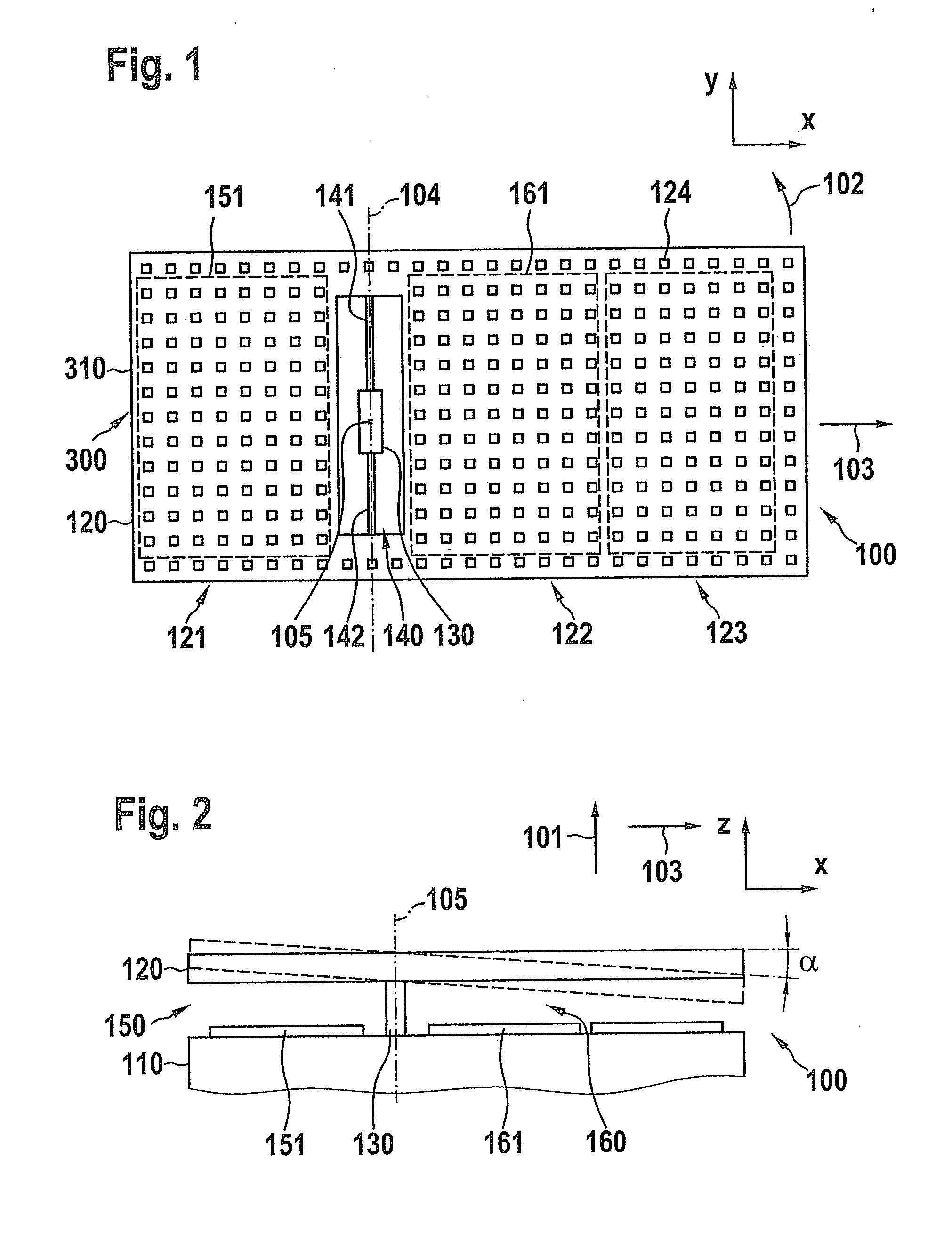
[0006]According to an example embodiment of the present invention, a micromechanical acceleration sensor is provided which includes a substrate and a seismic mass which is movably situated with respect to the substrate in a detection direction, the micromechanical sensor including at least one damping device for damping motions of the seismic mass perpendicular to the detection direction. The undesirable vibrations of the seismic mass may be effectively prevented with the aid of the damping device. In this way, among other things striking of the seismic mass is prevented or shifted to higher accelerations. Overall, an improvement on the vibration robustness and the overload resistance of a rocker-like z acceleration sensor may be achieved.
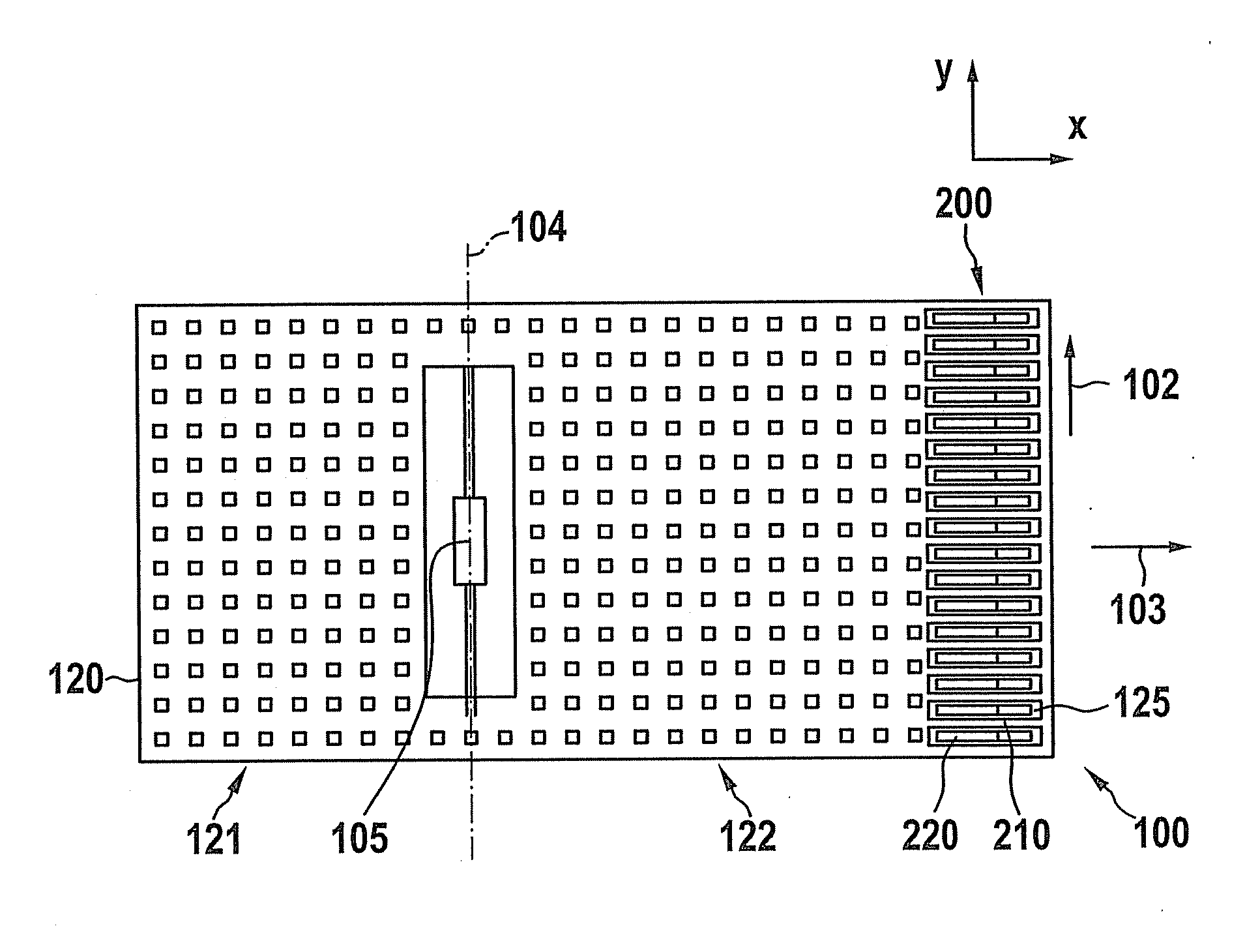
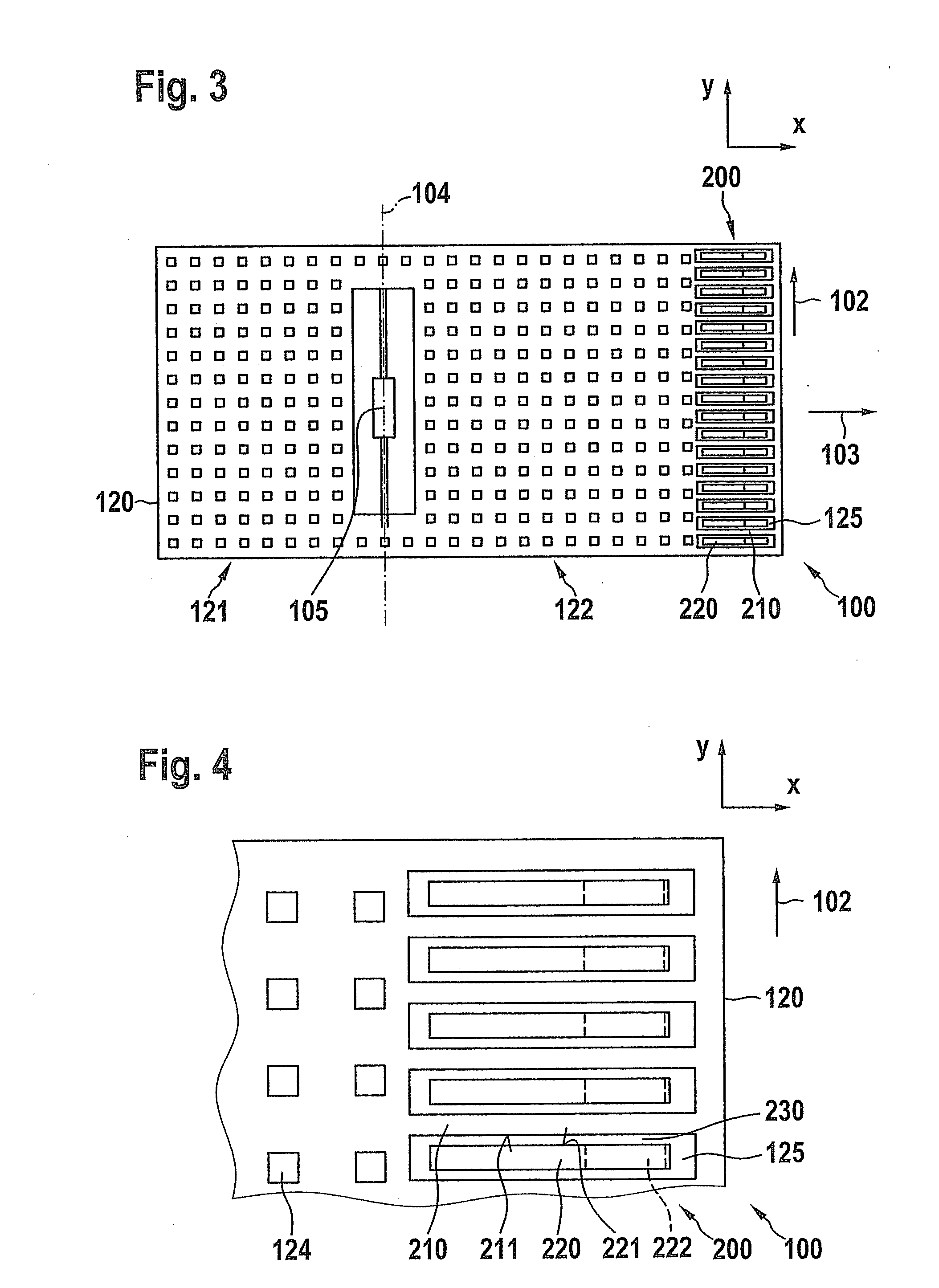
[0007]In another specific embodiment it is provided that the seismic mass includes at least one movable damping structure which, together with a stationary damping structure which is mounted on the substrate, forms a gas-filled damping gap having a predefined width, the damping structures being situated in relation to the detection direction in such a way that the width of the damping gap is reduced when the seismic mass moves perpendicular to the detection direction, causing squeezing of the gas in the damping gap. The squeeze film damping allows very effective damping of spurious vibrations in the plane perpendicular to the detection direction. The damping occurs passively, i.e., without the active intervention of devices. Effective damping may thus be provided in a very cost-effective manner.

Problems solved by technology

However, such a spring-mass system also responds to accelerations in the plane which is orthogonal to the preferred detection direction, resulting in undesirable vibrations of the sensor mass in this plane.
In the case of resonance, these vibrations may result in striking of the rocker, and thus, in interference signals in the range of the measuring range.
Two in-plane modes have proven to have a particularly adverse effect on the useful signal: namely, a rotational vibration of the sensor mass about a rotational axis parallel to the detection direction, and a translational vibration in the longitudinal direction of the mass.

Method used


Image

  • Acceleration sensor having a damping device
  • Acceleration sensor having a damping device
  • Acceleration sensor having a damping device

Examples


Embodiment Construction

[0029]FIGS. 1 and 2 show a typical z acceleration sensor having the so-called “rocker design.” Micromechanical sensor 100 illustrated in a top view in FIG. 1 is composed of a plate-shaped body 120 which is used as a seismic mass and which is deflectably suspended in a rocker-like manner with respect to a subjacent substrate 110 with the aid of an elastic suspension 140. Seismic mass 120 may be connected, for example, via two torsion springs 141, 142 to a central support structure 130 which is used as a suspension point for torsion springs 141, 142. The suspension of seismic mass 120 is selected in such a way that an additional mass 123 results on a rocker side 122 which causes a torque, and therefore a deflection a of rocker 120 from its neutral / zero position, when the sensor structure is accelerated perpendicular to the substrate plane. In the present example, the motion of rocker 120 is capacitively evaluated with the aid of two detection electrodes 151, 161, situated on either si...


PUM


Abstract

A micromechanical acceleration sensor is described which includes a substrate and a seismic mass which is movably situated with respect to the substrate in a detection direction. The micromechanical sensor includes at least one damping device for damping motions of the seismic mass perpendicular to the detection direction.

Description

CROSS REFERENCE[0001]The present application claims the benefit under 35 U.S.C. §119 of German Patent Application No. DE 102010039069.0, filed on Aug. 9, 2010, which is expressly incorporated herein by reference in its entirety.FIELD OF THE INVENTION[0002]The present invention relates to a micromechanical acceleration sensor having a seismic mass which is deflectable in a detection direction, and a damping device for damping undesirable motions of the seismic mass in a direction which is orthogonal to the detection direction.BACKGROUND INFORMATION[0003]Micromechanical sensors are used in various technical applications. Among others, capacitive acceleration sensors are used which have a detection direction perpendicular to the wafer plane (z direction) and which are designed in the form of a rocker. This sensor principle is based on a spring-mass system in which the motion of a suspended seismic mass which is elastically deflectable with respect to a substrate is capacitively detecte...

Claims


Application Information

Patent Timeline
Patent Type & Authority Applications(United States)
IPC IPC(8): G01P15/02
CPCG01P15/125G01P2015/0837G01P2015/0831G01P2015/0882
Inventor CLASSEN, JOHANNESGUENTHER, SEBASTIANSTEFFES, HARALD
Owner ROBERT BOSCH GMBH
Why Eureka
Eureka Blog
Learn More