Gripper having sensor for detecting displacement

a technology of detecting displacement and sensor, which is applied in the field of automatic handling equipment, can solve the problems of inconvenient adjustment, large amount of play, complex setup and use of sensor, etc., and achieve the effect of improving the accuracy of gripper jaw position determination

Active Publication Date: 2008-05-01
NORGREN AUTOMATION SOLUTIONS
View PDF10 Cites 26 Cited by
  • Summary
  • Abstract
  • Description
  • Claims
  • Application Information

AI Technical Summary

Benefits of technology

[0005]The disclosed example gripper assemblies and methods are for providing a relatively simpl

Problems solved by technology

As a result, setup and use of the sensor can be complex and require many adjustments.
Furthermore, for gripper jaws or other types of applicat

Method used


Image

  • Gripper having sensor for detecting displacement
  • Gripper having sensor for detecting displacement
  • Gripper having sensor for detecting displacement

Examples


Embodiment Construction

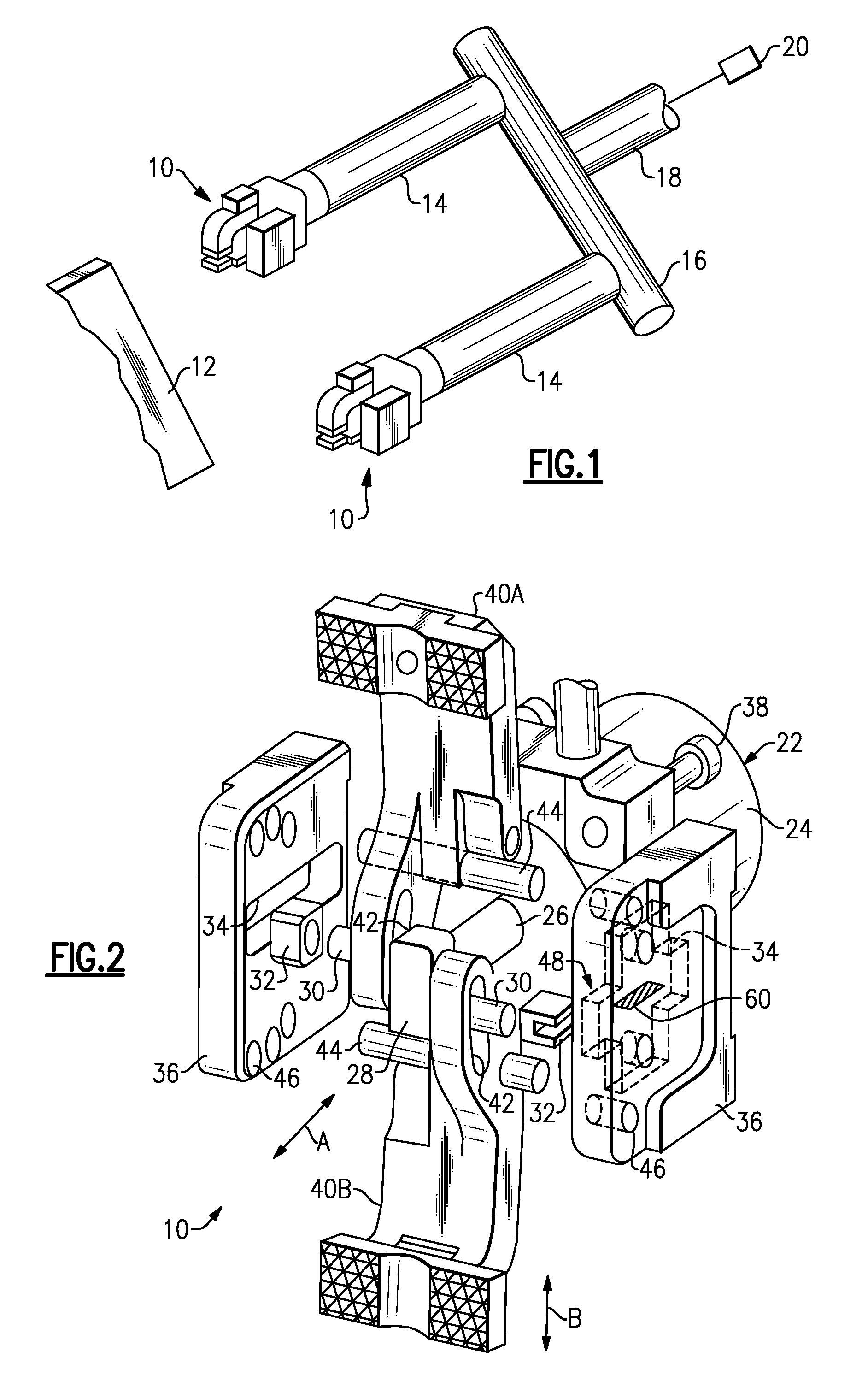
[0016]FIG. 1 illustrates selected portions of several automated gripper assemblies 10 used in an example industrial setting to grip and move a work piece 12 (shown schematically). The gripper assemblies 10 may be used in a variety of different configurations from that shown. In this example, the gripper assemblies 10 are coupled to extended arms 14, which are each secured to a rail 16. An adapter arm 18 is secured to the rail 16. An automated machine 20, such as a robot, moves the adapter arm 18, the extended arms 14, and the gripper assemblies 10 to desired positions to retrieve and deposit the work pieces 12, such as between work stations.

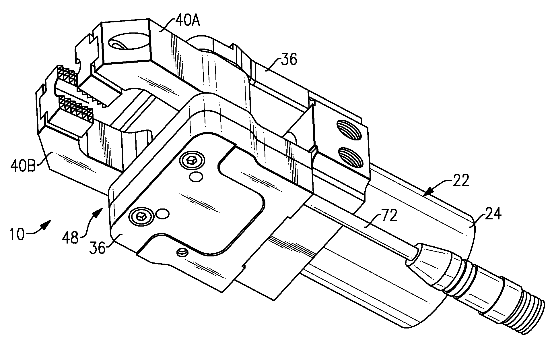
[0017]FIG. 2 illustrates selected portions of one of the gripper assemblies 10 shown in FIG. 1. Although FIG. 2 illustrates a particular gripper configuration, the examples disclosed herein may also be applied by workers in the art to other gripper configurations.

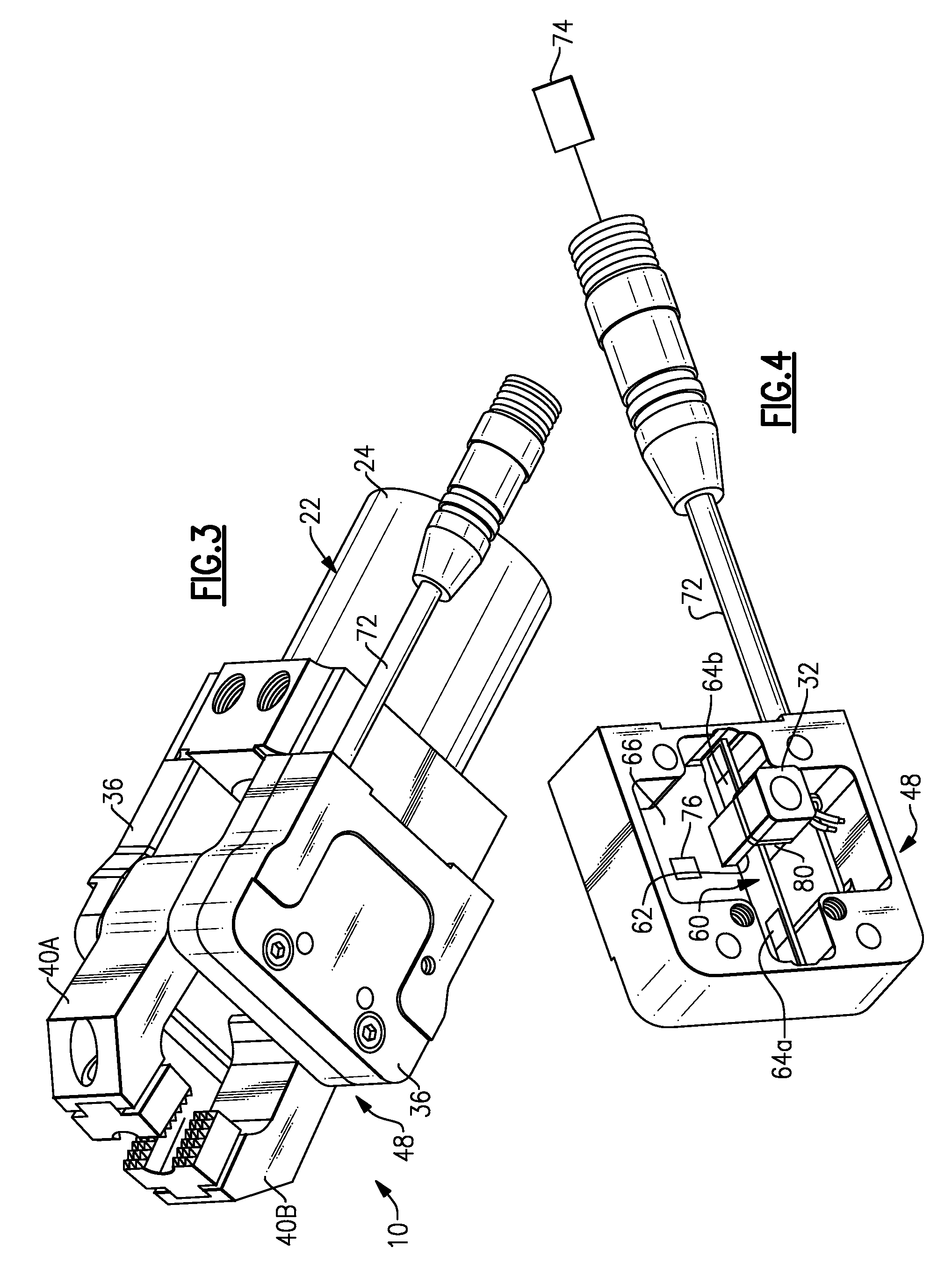
[0018]In the disclosed example, the gripper assembly 10 includes an actuator 22 havi...


PUM


Abstract

A gripper assembly includes at least one movable gripper jaw and a sensor member coupled for movement with the at least one gripper jaw. The sensor member includes a slot. A sensor is located at least partially within the slot and includes at least one inductor for inductively detecting a proximity of the sensor member.

Description

RELATED APPLICATIONS[0001]The application claims priority to U.S. Provisional Application No. 60 / 855,920, which was filed on Nov. 1, 2006.BACKGROUND OF THE INVENTION[0002]This invention relates generally to automated handling equipment and, more particularly, to a gripper system and method for detecting displacement of a gripper jaw using an inductor.[0003]Automated handling equipment is typically employed in industrial settings for transferring work pieces between work stations. Typically, the equipment includes a gripper that clamps onto work pieces while moving the work pieces between the stations. Conventional grippers include an actuator that moves one or more gripper jaws between open and closed jaw positions.[0004]Sensors, such as mechanical proximity sensors or displacement sensors, have been employed within gripper assemblies to detect jaw position or a displacement between gripper jaws. Typically, the accuracy of a mechanical proximity sensor or a displacement sensor is se...

Claims


Application Information

Patent Timeline
IPC IPC(8): B65H5/14B65H1/00G05B15/02
CPCB25J15/0226B25J19/027G01D5/202B65H2553/24B65H5/14Y10S294/907
Inventor HOLCOMB, MARKWALDORF, CONRADCHARLTON, JOHN
Owner NORGREN AUTOMATION SOLUTIONS
Why Eureka
Try Eureka