Volume charge density measuring system

a density measurement and volume charge technology, applied in the direction of resistance/reactance/impedence, measurement devices, instruments, etc., can solve the problem of not being able to consistently measure ion concentrations in water below a few parts per million, for exampl

Inactive Publication Date: 2003-07-01
JOFRACH L L C
View PDF27 Cites 24 Cited by
  • Summary
  • Abstract
  • Description
  • Claims
  • Application Information

AI Technical Summary

Problems solved by technology

They cannot, for example, consistently measure ion c

Method used


Image

  • Volume charge density measuring system
  • Volume charge density measuring system
  • Volume charge density measuring system

Examples


Embodiment Construction

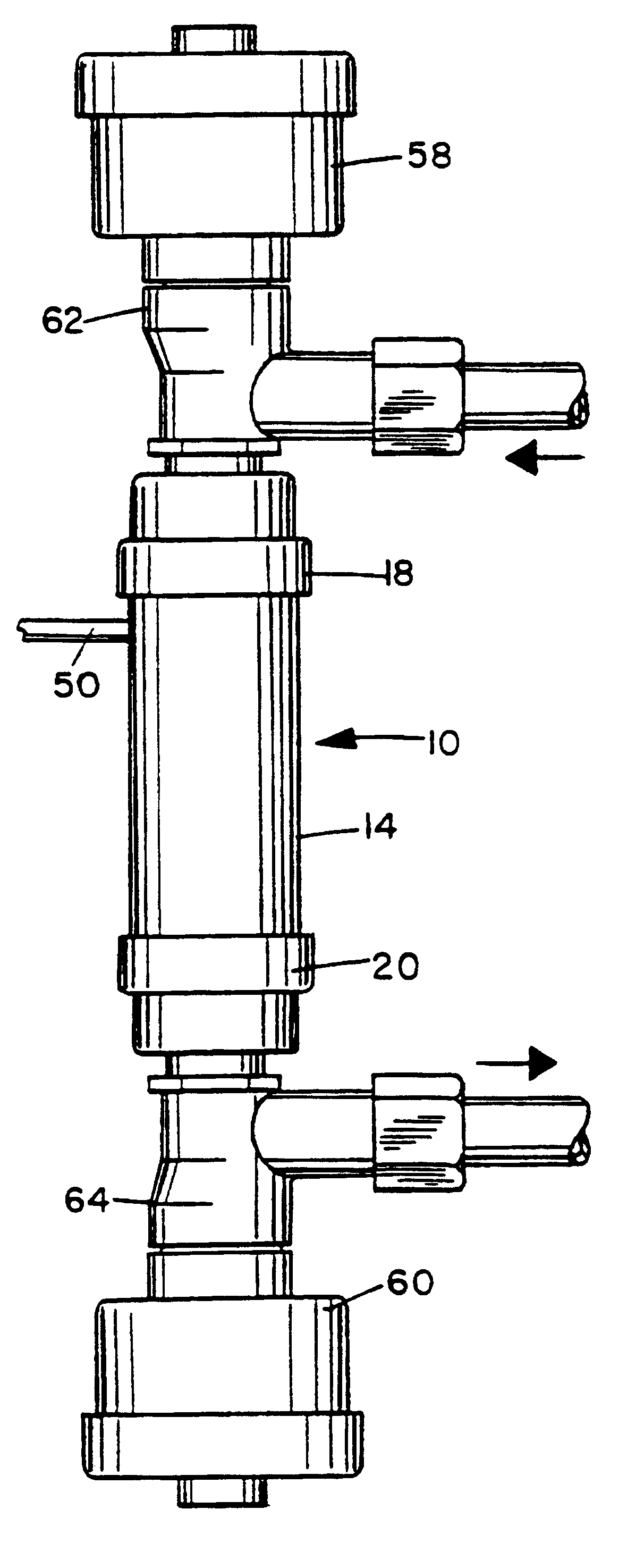
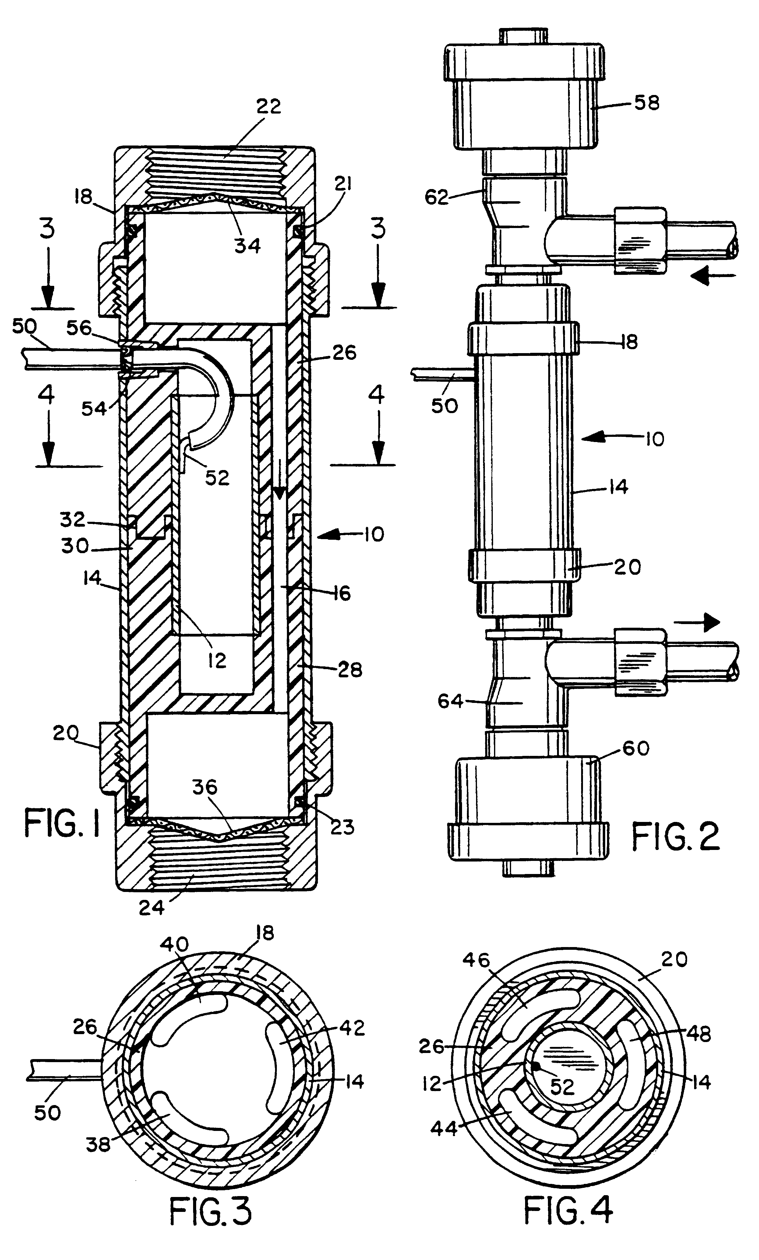
As illustrated in FIGS. 1-4, a capacitive sensor 10 includes an elongated, generally tubular inner conductor 12 and an elongated, generally tubular outer conductor 14 that are coaxially or concentrically mounted with respect to one another. Conductors 12 and 14 are radially spaced from one another, thereby defining an elongated annular chamber 16. Outer conductor 14 includes two conductive endpieces 18 and 20, one threadably attached to each end of sensor 10. O-rings 21 and 23 seal endpieces 18 and 20, respectively, against leakage. Endpieces 18 and 20 have sensor inlet and outlet openings 22 and 24, respectively. As more fully described below, sensor 10 may be used to measure the volume charge density of a fluid, i.e., a liquid or gas in chamber 16, which may flow into sensor inlet opening 22 and out of sensor outlet opening 24.

Two body portions 26 and 28 made of a non-conductive material are disposed at opposite ends of sensor 10. Body portion 26 is fit within one end of outer con...


PUM


Abstract

A capacitive sensor is shielded against external electric fields to maximize measurement accuracy. The sensor may include two coaxial, tubular conductors with a chamber between them into which a material sample to be measured is introduced. A measurement circuit connected to the sensor may include a reference oscillator that oscillates at a constant frequency and a test oscillator that oscillates at a frequency responsive to sensor capacitance. The circuit may display a value responsive to the difference between the test and reference frequencies. The circuit may also reverse the polarity of the signal applied to the sensor to minimize charge buildup, a phase-locked loop frequency measuring circuit, a temperature compensating circuit, and a non-linearity compensating circuit. The indicating circuit that displays a representation of the measured capacitance may display a continuous-scale or proportional representation or may display a binary or "go-nogo" representation. An alternative sensor of the system includes coaxial, finned inner and outer conductors that intermesh to maximize capacitive surface area. Another alternative sensor includes two parallel, plate-like conductors. The sensor system may be used to measure volume charge density of a fluid or parameters responsive to changes in volume charge density, such as flow velocity.

Description

2. Field of the InventionThe present invention relates generally to capacitive measuring systems and, more specifically, to systems having a sensor shielded against the detrimental effects of external electric fields and circuits for capacitively measuring the volume charge density of a sample of material.2. Description of the Related ArtCapacitive measuring systems have been used to measure dissolved solids and impurities in fluids such as water and oil. A capacitive sensor is a device having two electrically conductive electrodes and a non-conductive body that insulates the fluid from the electrodes. The electrodes are typically tubular in shape and concentric with one another. When a sample is placed in the body, the device defines a capacitance in response to the dielectric constant of the sample. The dielectric constant varies in response to the ion concentration in the sample, which, in turn, is related to the solid impurities. The capacitance may be measured by connecting a s...

Claims


Application Information

Patent Timeline
IPC IPC(8): G01R15/14G01R15/16
CPCG01R15/16
Inventor SARGENT, JOHN S.SARGENT, FRANK T.
Owner JOFRACH L L C
Why Eureka
Try Eureka