Lancet Instrument

a technology of lancet and casing, which is applied in the field of lancet instruments, can solve the problems of weakened engagement between the lancet and the casing, skin or the like of patients, for example, may be injured by mistak

Active Publication Date: 2008-05-01
TERUMO KK
View PDF12 Cites 101 Cited by
  • Summary
  • Abstract
  • Description
  • Claims
  • Application Information

AI Technical Summary

Benefits of technology

[0009]It is an object of the present invention to provide a lancet instrument wherein the

Problems solved by technology

However, in the lancet instrument thus configured, the engagement between the lancet and the casing may be weakened (due to a decrease of the frictional force) due, for example, to vibration or the like, and the lancet may be moved (displaced) toward the open

Method used


Image

  • Lancet Instrument
  • Lancet Instrument
  • Lancet Instrument

Examples


first embodiment

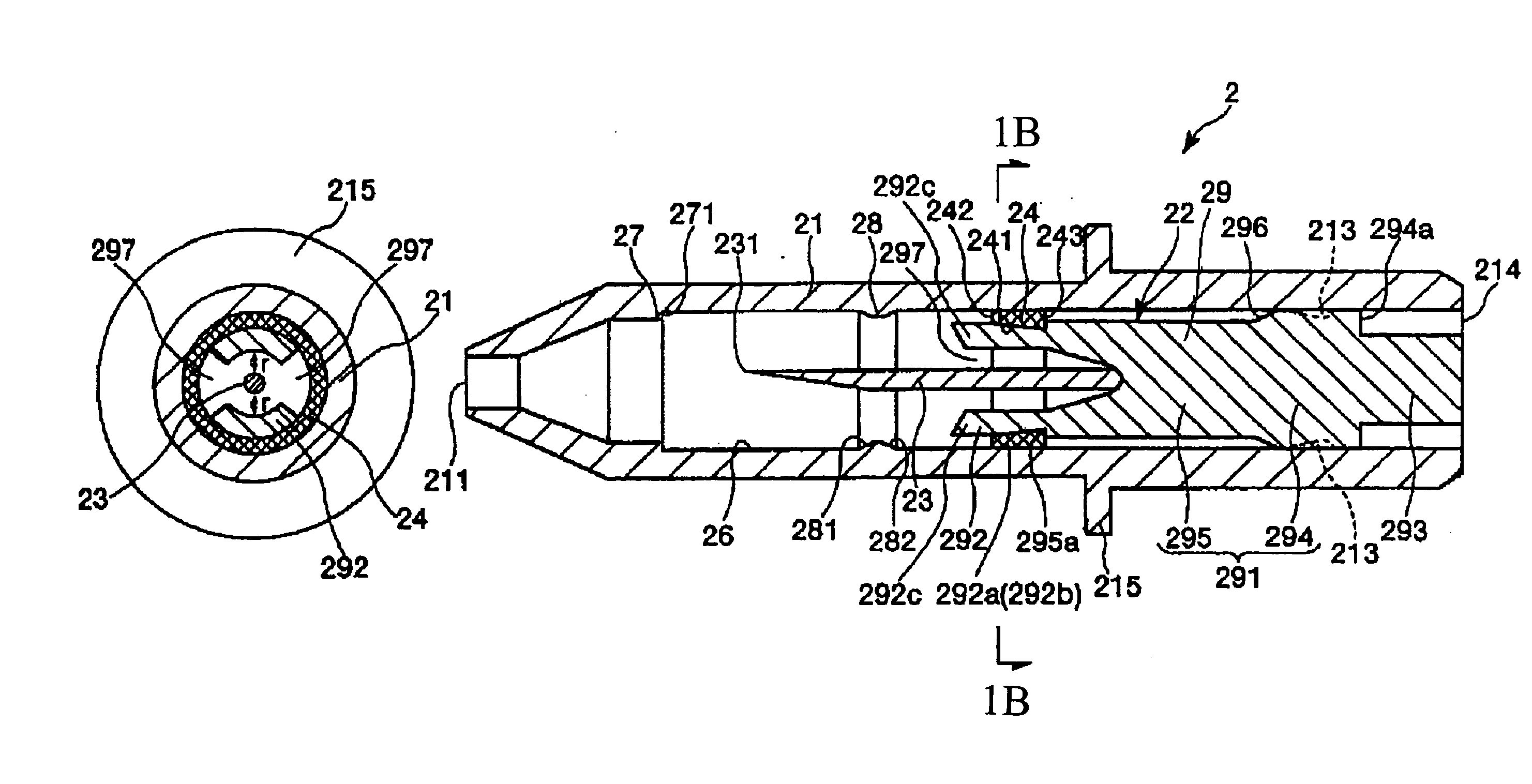
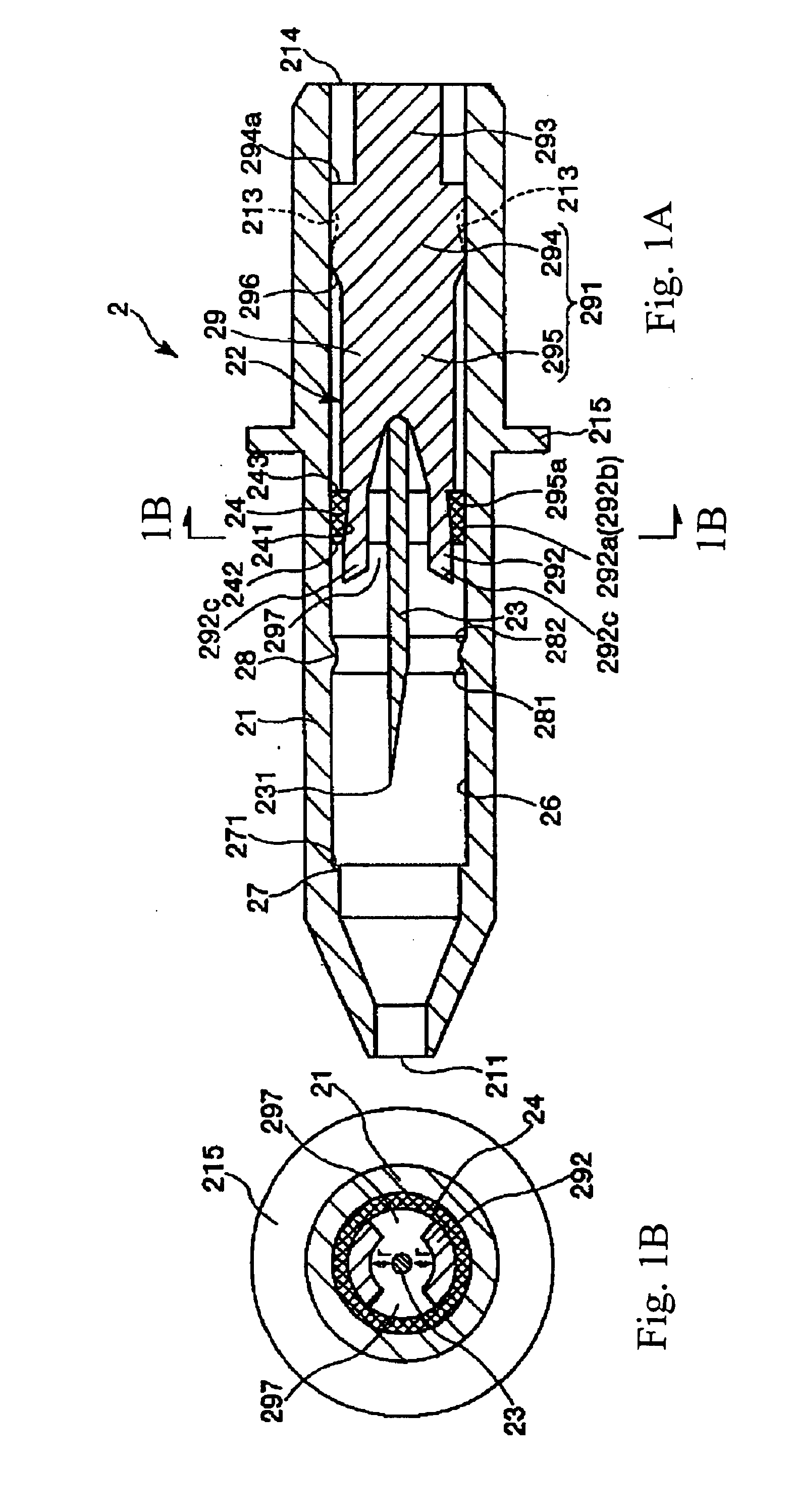
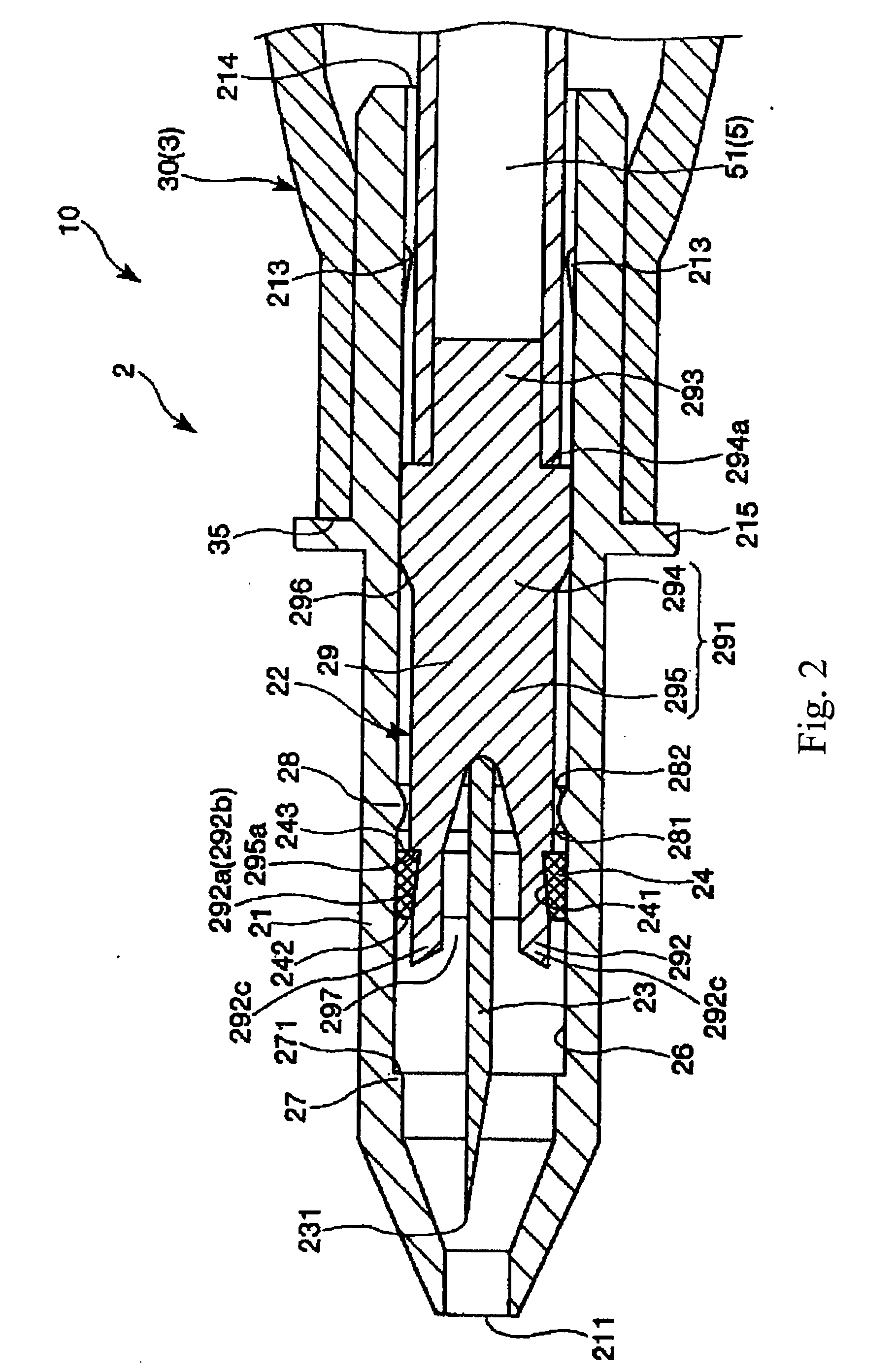
[0034]FIGS. 1 to 5 are longitudinal sectional views showing a first embodiment of the lancet instrument according to the present invention, FIGS. 6 and 7 are views (longitudinal views) for illustrating the method of using the lancet instrument (first embodiment) according to the invention by fitting it to a lancing apparatus, and FIGS. 8A and 8C are end views and FIG. 8B is a side view showing the configuration of an adjusting part provided in the lancing apparatus shown in FIGS. 6 and 7. Incidentally, hereinafter, description will be made by referring to the left side in FIGS. 1 to 7 as “the tip”, and the right side as “the base end”.

[0035]A lancet instrument 2 shown in FIGS. 1 to 5 is used in the state of being detachably fitted to a lancing apparatus 10 as shown in FIGS. 6 and 7. The lancet instrument 10 has an elongate housing 3, a plunger 5, an adjusting part 6, a lancing operating part (operating means) 7, a set operating part (operating part) 8, a coil spring 91 biasing the p...

second embodiment

[0154]FIG. 9 is a longitudinal sectional view showing a second embodiment of the lancet instrument according to the present invention. Incidentally, hereinafter, the description will be made by referring to the left side in FIG. 9 as the “tip”, and the right side as the “base end”.

[0155]Now, referring to this figure, the second embodiment of the lancet instrument according to the present invention will be described. The following description will be focused on the differences from the above-described embodiment, and descriptions of the same items as above will be omitted.

[0156]This embodiment is the same as the first embodiment, except for the shape of the ring-like member.

[0157]As shown in FIG. 9, a ring-like member 24A of a lancet instrument 2A is provided at its base end face 243 with a ring-like recess 245 concentric with the ring-like member 24A.

[0158]The recess 245 is wedge-shaped in section, and has a slant surface (bottom surface) 246 inclined against the base end face 243, ...


PUM


Abstract

A lancet instrument detachably fitted to a lancing apparatus, comprising a lancet having a lancet body with a sharp lancet tip at its tip, a lancet hub fixed to the lancet body so that the lancet tip is exposed, and an elastic deformation part extended from the lancet hub in the tip direction and elastically deformable so that the distance thereof from the lancet body can be changed, a ring-like member fitted to the outer periphery of the elastic deformation part and releasable in the tip direction by changing the distance between the elastic deformation part and the lancet body, and a casing having a ring-like member contact part storing the lancet so as to be movable in the longitudinal direction and formed in the inner peripheral part thereof so that the ring-like member is brought into contact therewith and stopped to move in the tip direction and a tip opening through which the lancet tip can be projected. The lancet instrument thus obtained is so formed that the projection of the lancet tip through the tip opening of the casing is blocked by moving the ring-like member released from the elastic deformation part in the tip direction between the tip of the elastic deformation part and the ring-like member contact part to restrict the movement of the lancet.

Description

TECHNICAL FIELD[0001]The present invention relates to a lancet instrument.BACKGROUND ART[0002]In recent years, accompanying the increase in the number of diabetics, the self monitoring of blood glucose monitoring daily movements in blood sugar level by the patient himself has come to be recommended.[0003]The measurement of blood sugar level is carried out by use of a blood glucose monitoring apparatus for automatically measuring the amount of glucose in blood. Prior to the measurement, the patient must sample his own blood.[0004]A method of sampling blood includes the steps of puncturing the skin of a fingertip by a lancet and then pressing the vicinity of the puncture portion with fingers or the like to squeeze out the blood.[0005]The puncture of a fingertip with a lancet is conducted by use of a lancet instrument (refer to, for example, U.S. Pat. No. 6,540,762) having a lancet and a casing (cap) storing the lancet movably therein. Specifically, the lancet instrument is fitted to t...

Claims


Application Information

Patent Timeline
IPC IPC(8): A61B17/32
CPCA61B5/1411A61B5/150022A61B5/15019A61B5/150259A61B5/150412A61B5/150503A61B5/150916A61B5/15113A61B5/15117A61B5/1519A61B5/15194A61B5/150832
Inventor TAKEMOTO, MASAFUMIYAZAKI, HIROFUMI
Owner TERUMO KK
Why Eureka
Try Eureka