
Method and apparatus for inhibiting pitch formation in the wet seal exhaust duct of a veneer dryer

a dryer and wet seal technology, applied in the direction of drying machines with progressive movements, lighting and heating apparatus, furnaces, etc., can solve the problems of insufficient maintenance and cleaning practices, insufficient pitch formation, and inability to properly control the exhaust control

Active Publication Date: 2008-05-08
USNRKOCKUMS CANCAR +1
View PDF8 Cites 6 Cited by
  • Summary
  • Abstract
  • Description
  • Claims
  • Application Information

AI Technical Summary

Benefits of technology

The present invention is about a better way to control a dryer used to remove moisture from sheet materials like veneer. It helps to heat the air that comes out of the dryer so that it can remove more moisture from the material. This makes the drying process faster and more effective.

Problems solved by technology

The technical problem addressed in this patent is the need to improve the drying efficiency of a conveyor dryer by controlling the flow of exhaust gases and containing and treating them prior to discharging to atmosphere. The patent also addresses the issue of pitch build-up and condensed V.O.C. material in the exhaust fan duct, which may result in a fire hazard.

Method used


Image

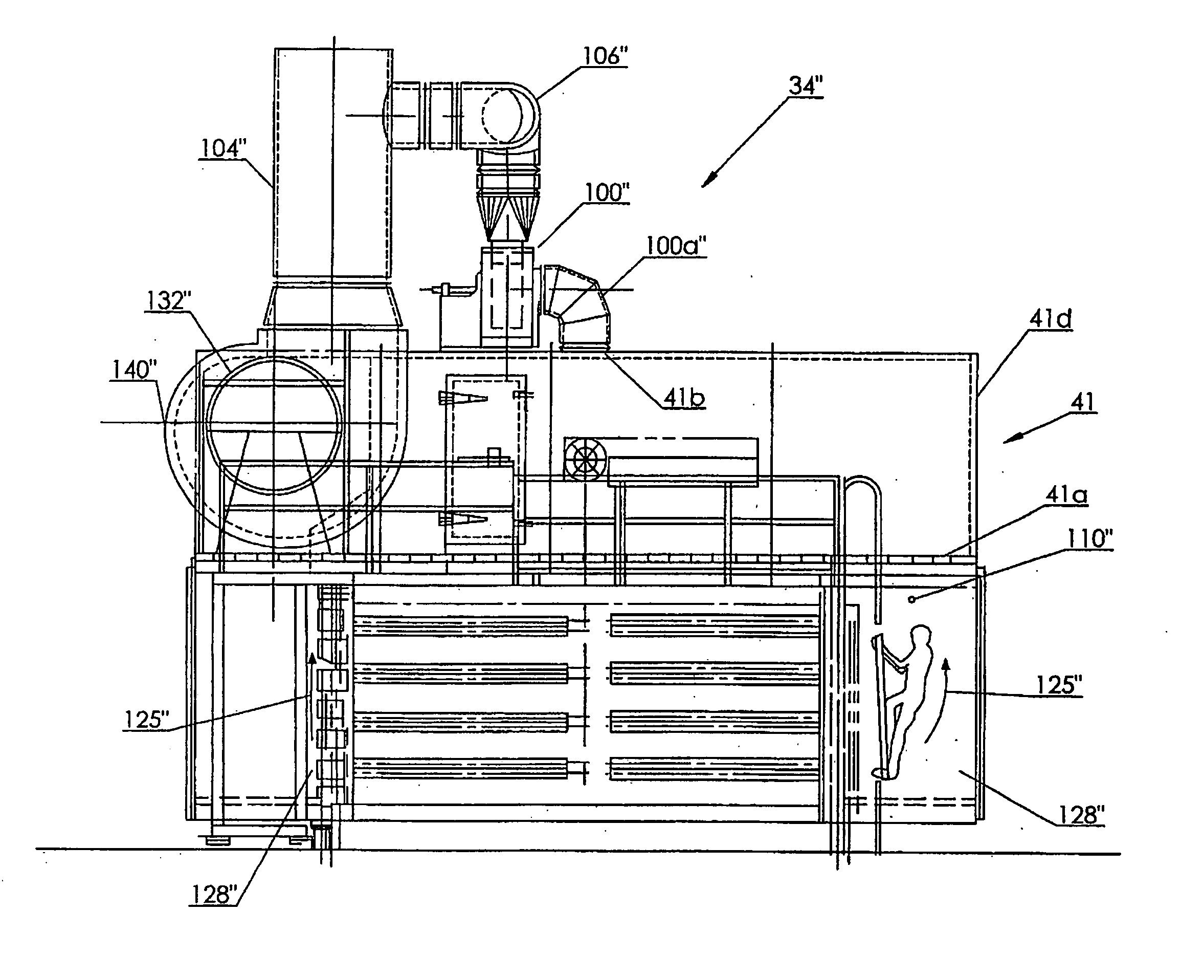
  • Method and apparatus for inhibiting pitch formation in the wet seal exhaust duct of a veneer dryer
  • Method and apparatus for inhibiting pitch formation in the wet seal exhaust duct of a veneer dryer
  • Method and apparatus for inhibiting pitch formation in the wet seal exhaust duct of a veneer dryer

Examples


Embodiment Construction

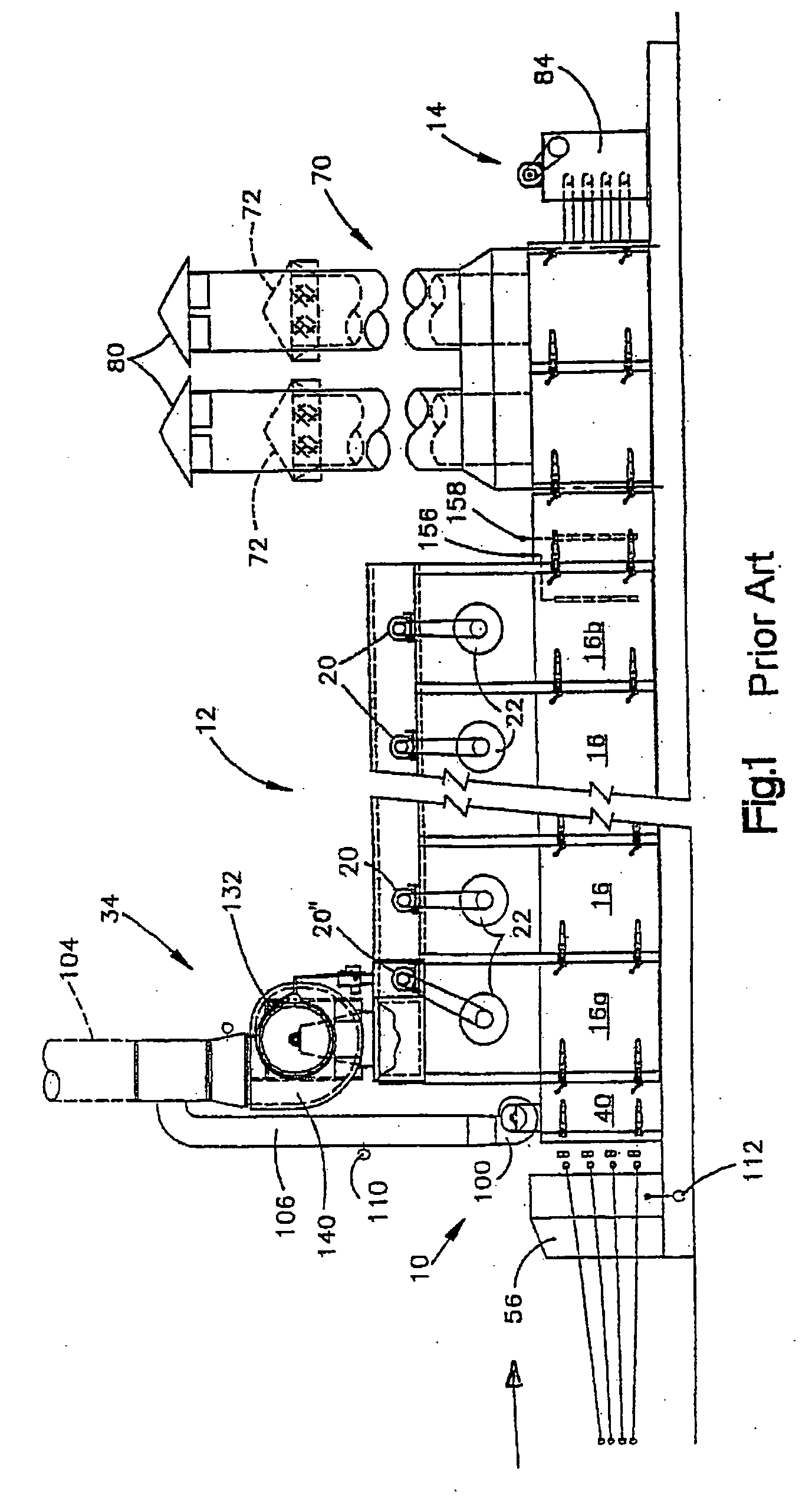
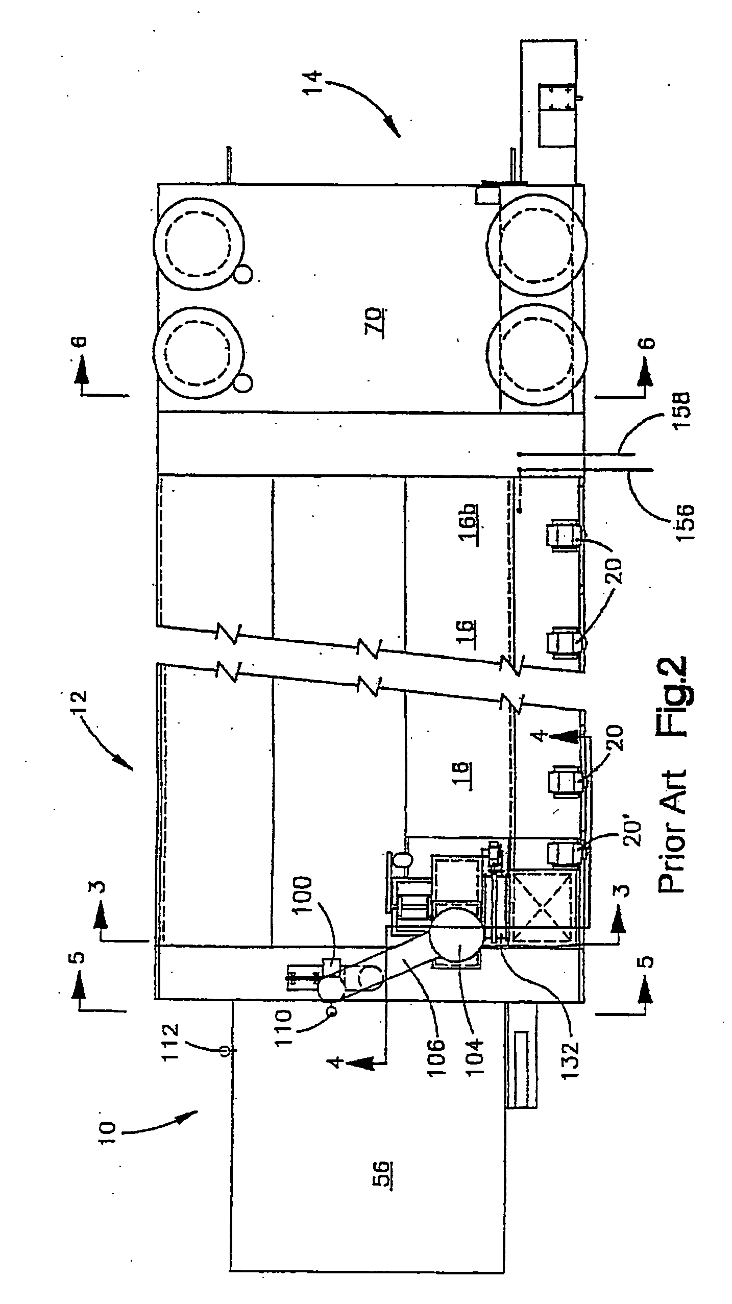
[0037] As disclosed in U.S. Pat. No. 5,603,168, FIGS. 1 and 2 illustrate the overall construction of a jet veneer dryer. A “jet veneer dryer” is the type of dryer which is used to reduce the moisture content of, or dry, sheet material, such as wood veneers, pulp board, plasterboard, fiberboard, perlite board, and the like. The material to be dried is introduced at a “wet end”10 of the apparatus, is conveyed through a drying chamber 12, ultimately exiting the apparatus at a “dry end”14.

[0038] The illustrated prior art dryer includes a plurality of juxtaposed, drying sections 16 which, in the illustrated embodiment, are virtually identical. Each drying section 16 is considered conventional and includes a drive motor 20 for driving an axial-type fan 22 which circulates air within the drying section in a circular path, transverse to the path of movement of material through the drying chamber 12.

[0039] As moisture is driven from the material passing through the chamber 12, the volume o...


PUM


Abstract

A method and apparatus for operating a dryer used to reduce the moisture content of sheet material. A drying chamber is provided and includes a plurality of drying sections and a single point exhaust system. A seal section located at the input end of the dryer includes an exhaust passage through which a gas sample is drawn by a sampling fan. Gases within the seal section are a combination of ambient air drawn through restricted passages at the entry to the seal section and exhaust gas that bleeds into the seal section from the drying chamber. A controller monitors the temperature of the sampled gases and ambient air and adjusts the rate of exhaust flow from the main exhaust system as a function of the temperature differential. A heating system is also provided for heating the seal exhaust gases above the pitch condensation temperature for the flow.

Description


Claims


Application Information

Patent Timeline
Owner USNRKOCKUMS CANCAR
Learn More