Liquid-Vapor Separator For A Minichannel Heat Exchanger

a minichannel heat exchanger and liquid-vapor separator technology, which is applied in the direction of refrigeration machines, compression machines with several evaporators, lighting and heating apparatus, etc., can solve the problems of significant evaporator and overall system performance degradation, improper heat exchanger orientation, and possible misdistribution of refrigeran

Inactive Publication Date: 2008-05-08
CARRIER CORP
View PDF48 Cites 29 Cited by
  • Summary
  • Abstract
  • Description
  • Claims
  • Application Information

AI Technical Summary

Benefits of technology

[0010]Briefly, in accordance with one aspect of the invention, a liquid-vapor separator is provided between the expansion device and the inlet header such that the separator causes the refrigerant vapor to pass directly to the compressor and only liquid refrigerant to pass to the inlet manifold. In this way, a more uniform distribution of liquid refrigerant to the individual parallel channels is obtained.

Problems solved by technology

It causes significant evaporator and overall system performance degradation over a wide range of operating conditions.
Maldistribution of refrigerant may occur due to differences in flow impedances within evaporator channels, non-uniform airflow distribution over external heat transfer surfaces, improper heat exchanger orientation or poor manifold and distribution system design.
Attempts to eliminate or reduce the effects of this phenomenon on the performance of parallel flow evaporators have been made with little or no success.
The primary reasons for such failures have generally been related to complexity and inefficiency of the proposed technique or prohibitively high cost of the solution.
The evaporator applications, although promising greater benefits and rewards, are more challenging and problematic.
Refrigerant maldistribution is one of the primary concerns and obstacles for the implementation of this technology in the evaporator applications.
As known, refrigerant maldistribution in parallel flow heat exchangers occurs because of unequal pressure drop inside the channels and in the inlet and outlet manifolds, as well as poor manifold and distribution system design.
Furthermore, the recent trend of the heat exchanger performance enhancement promoted miniaturization of its channels (so-called minichannels and microchannels), which in turn negatively impacted refrigerant distribution.
Since it is extremely difficult to control all these factors, many of the previous attempts to manage refrigerant distribution, especially in parallel flow evaporators, have failed.
If, on the other hand, the velocity of the two-phase flow entering the manifold is low, there is not enough momentum to carry the liquid phase along the header.
Also, the liquid and vapor phases in the inlet manifold can be separated by the gravity forces, causing similar maldistribution consequences.
In either case, maldistribution phenomenon quickly surfaces and manifests itself in evaporator and overall system performance degradation.
Neither of these approaches are practical in minichannel or microchannel applications, wherein the channels are relatively small and closely spaced such that the individual restrictive devices could not, as a practical manner, be installed within the respective channels during the manufacturing process.

Method used


Image

  • Liquid-Vapor Separator For A Minichannel Heat Exchanger
  • Liquid-Vapor Separator For A Minichannel Heat Exchanger
  • Liquid-Vapor Separator For A Minichannel Heat Exchanger

Examples


Embodiment Construction

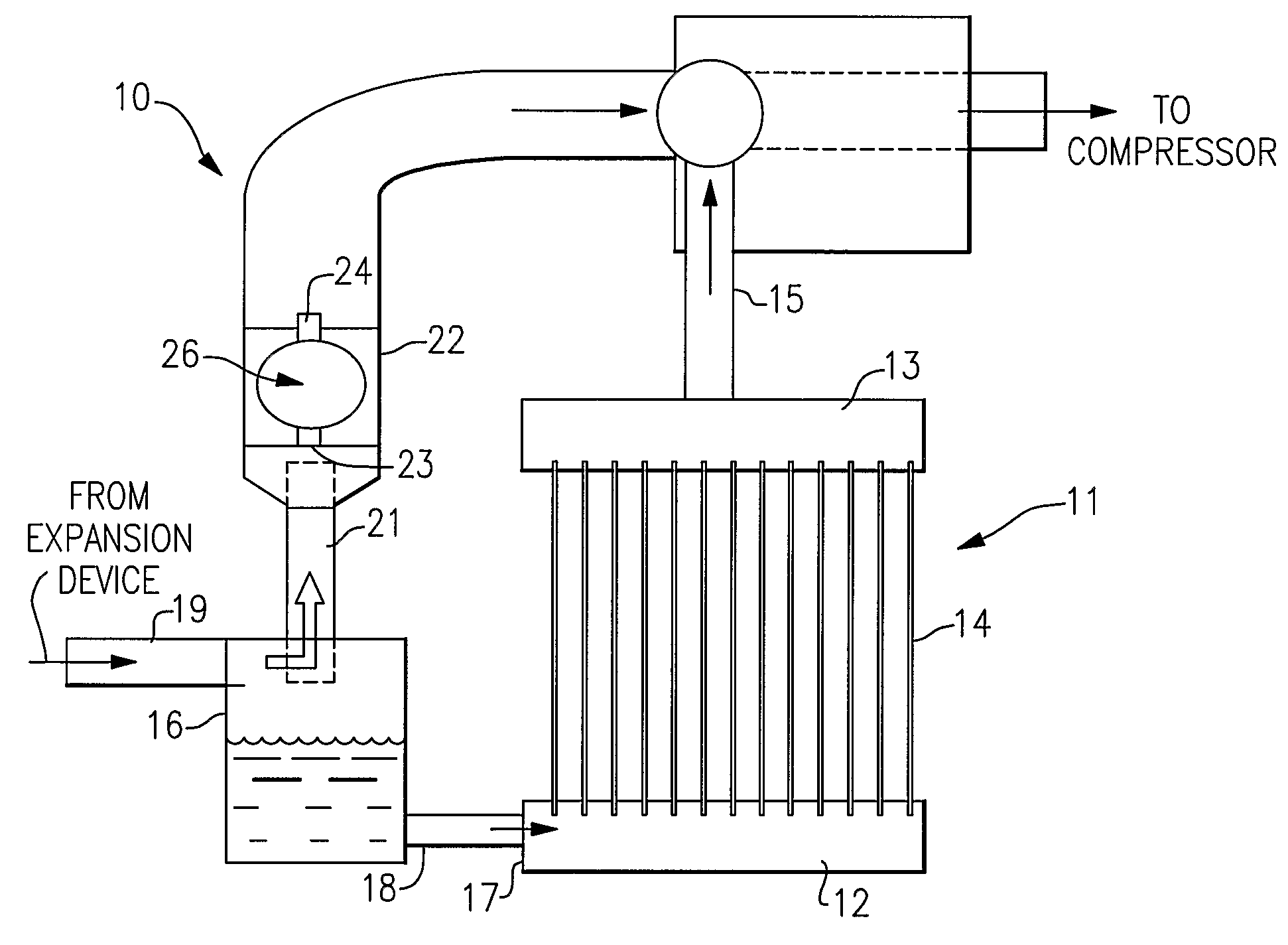
[0018]Referring now to FIG. 1, the invention is shown generally at 10 as applied to a minichannel heat exchanger 11 having an inlet manifold 12, an outlet manifold 13, and a plurality of parallel microchannels 14 interconnecting the inlet manifold 12 to the outlet manifold 13.

[0019]An inlet chamber 16 is fluidly connected to the upstream end 17 of the inlet manifold 12 by way of conduit 18. At an upper portion of the inlet chamber 16 an inlet line 19 provides fluid communication from an expansion device such that a mixture of liquid and vapor refrigerant flows into the upper portion of the inlet chamber 16. The heavier liquid refrigerant tends to fall to the bottom of the inlet chamber 16 and flow through the conduit 18 to the inlet manifold 12 such that each of the parallel minichannels 14 have single phase liquid refrigerant presented at their inlet ends.

[0020]Also connected at the upper portion of the inlet chambers 16 is a bypass duct 21 for conducting the flow of refrigerant va...


PUM


Abstract

A method and apparatus for promoting uniform refrigerant flow in a minichannel heat exchanger by providing a liquid-vapor separator between an expansion device and the inlet header such that the refrigerant vapor will pass directly to the compressor and only the liquid refrigerant will pass to the inlet header. The liquid-vapor separation is accomplished by way of a float valve which prevents the flow of liquid refrigerant to the compressor and the flow of refrigerant vapor from the outlet manifold, through the valve and back to the inlet manifold. A second float valve may be provided between a downstream end of the inlet manifold and the compressor for the purpose of removing any residual vapor from the liquid.

Description

BACKGROUND OF THE INVENTION[0001]This invention relates generally to air conditioning and refrigeration systems and, more particularly, to parallel flow evaporators thereof.[0002]A definition of a so-called parallel flow heat exchanger is widely used in the air conditioning and refrigeration industry now and designates a heat exchanger with a plurality of parallel passages, among which refrigerant is distributed and flown in the orientation generally substantially perpendicular to the refrigerant flow direction in the inlet and outlet manifolds. This definition is well adapted within the technical community and will be used throughout the text.[0003]Refrigerant maldistribution in refrigerant system evaporators is a well-known phenomenon. It causes significant evaporator and overall system performance degradation over a wide range of operating conditions. Maldistribution of refrigerant may occur due to differences in flow impedances within evaporator channels, non-uniform airflow dis...

Claims


Application Information

Patent Timeline
IPC IPC(8): F25B43/00
CPCF25B41/04F25B41/043F25B2600/2501F25B2400/0409F25B2400/23F25B43/006F25B41/22F25B43/02F25B43/00
Inventor GORBOUNOV, MIKHAIL B.SAHM, MICHAEL K.VERMA, PARMESH
Owner CARRIER CORP
Why Eureka
Try Eureka