

Tandem supersonic ejectors
a supersonic ejector and tandem technology, applied in the field of gas recovery and recompression, can solve the problems of patents that do not teach the use of gas ejectors to recycle off gases, patents that do not teach tandem supersonic ejectors,
- Summary
- Abstract
- Description
- Claims
- Application Information
AI Technical Summary
Benefits of technology
Problems solved by technology
Method used
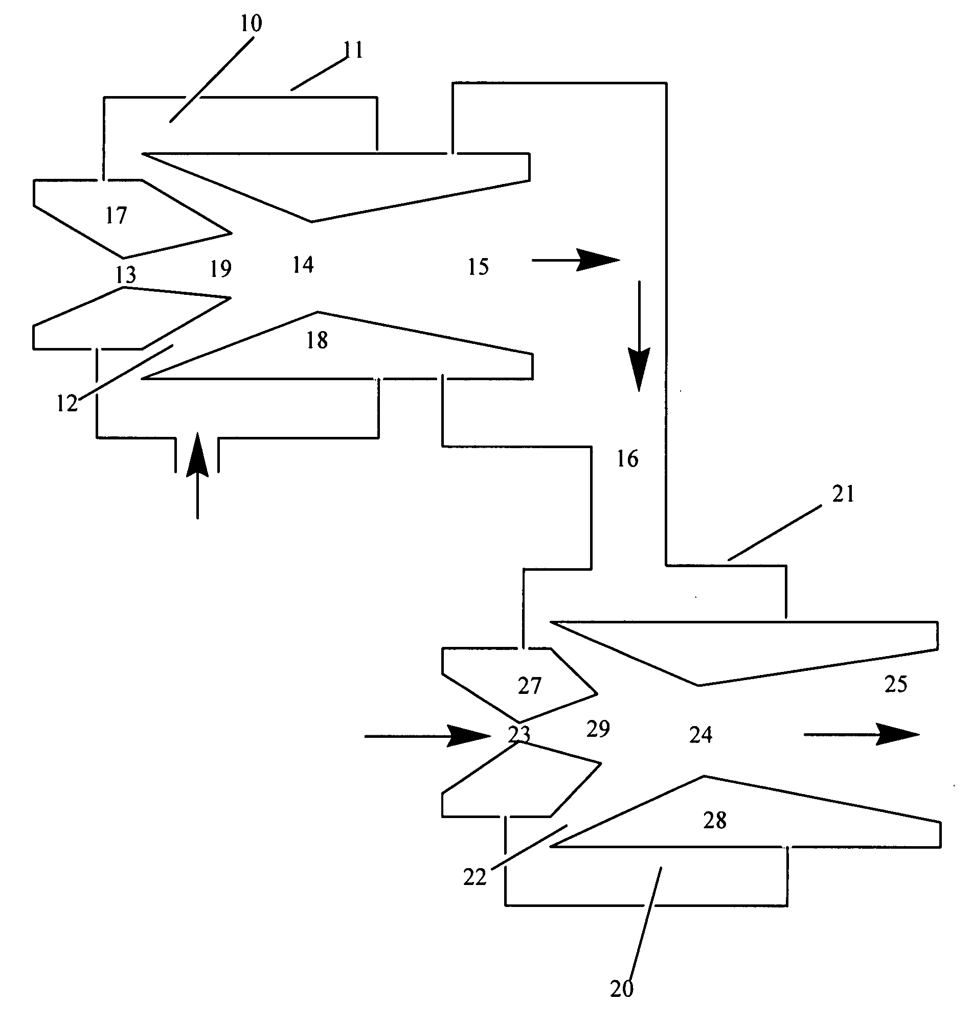
Image

Examples
example 1
Computational Fluid Dynamics
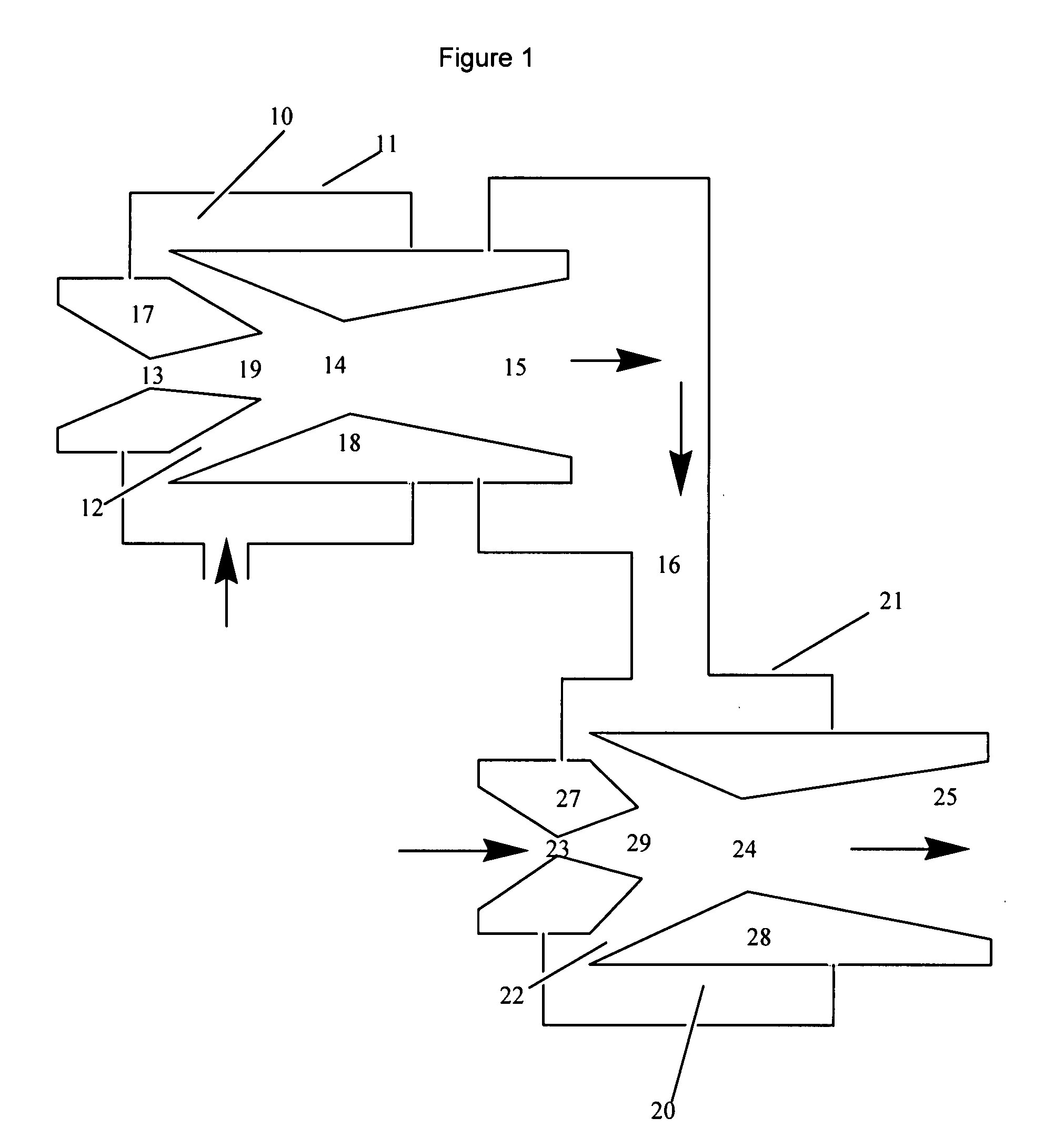
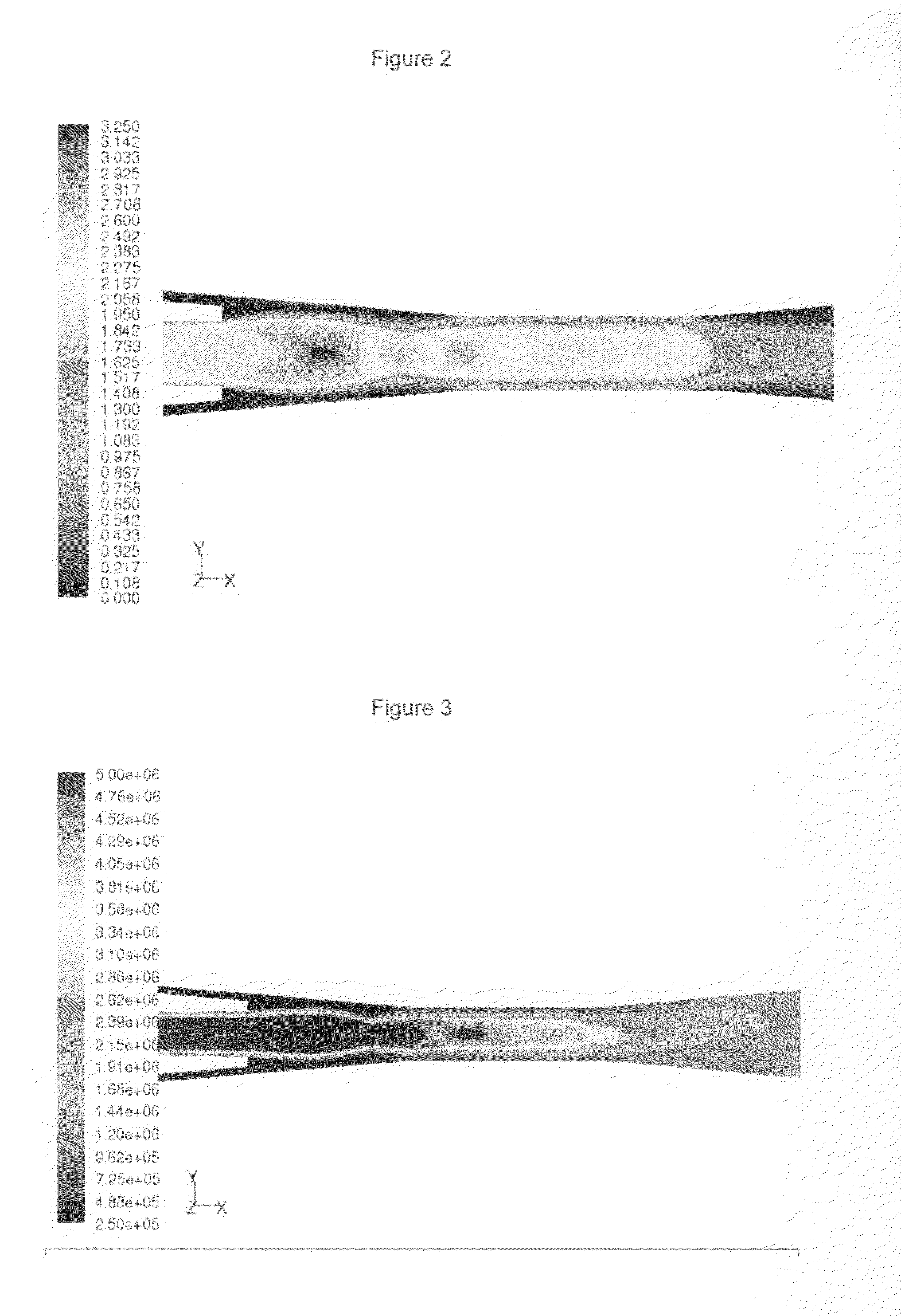
[0055]In order to arrive at the optimum design of a fixed-geometry diffuser that could work with different nozzles of different throat areas, Computational Fluid Dynamics (CFD) analysis was carried out to discern the flow field. FIGS. 2 and 3 show an example of CFD results showing the Mach number and stagnation pressure at nozzle exit and through the diffuser. This is an example of an optimized nozzle / diffuser arrangement showing that the nozzle is clear from a standing shock wave, which is good for suction. It is also shown that the shock wave region (which is the region were Mach number drops sharply from supersonic to subsonic—FIG. 2) is located at the throat of the diffuser or slightly downstream. This is also preferable for minimum stagnation pressure losses, as is also confirmed by the stagnation pressure contours of FIG. 3.
[0056]In order to further assess the efficiency of the ejector (combined of both elements: nozzle and diffuser), the following ...
example 2
First Supersonic Ejector
[0057]Based on the above calculations, and in order to satisfy the relatively low suction pressure to match the dry-gas seal leakage pressure (˜400 kPa-a), an ejector with a highly supersonic exit flow was employed. A flexible prototype design was fabricated which allows for various geometry supersonic nozzles to be tested with a fixed geometry diffuser, but it also allows for fine adjustments of the position of the nozzle exit in relation to the diffuser inlet (either positively, i.e. inserted into the diffuser inlet section, or negatively, i.e. retrieved back with a gap in between nozzle exit and diffuser inlet).
[0058]The supersonic diffuser has an inlet diameter of 4 mm, a throat diameter of 3.5 mm and length of 8 mm, and an exit diameter of 18 mm. Inlet ½-angle of the inlet section is 4.7°, while that of the exit section is 5°. Several supersonic converging / diverging nozzles were fabricated with different throat diameters and exit / throat area ratios as sh...
example 3
Second Stage Ejector
[0062]Computational Fluid Dynamics (CFD) was utilized to optimize the best supersonic diffuser dimensions (throat, inlet, and outlet diameters, as well as angles) and position of the nozzle with respect to the diffuser inlet. Table 4 shows the optimum design for the second stage ejector.
TABLE 4Characteristic Dimensions of the 2nd Stage EjectorNozzle Diametermm7.4Nozzle Exitmm8.7Half Angledeg1Diffuser Inlet Diamtermm12.4Half Angledeg1Diffuser Throat Diametermm10Diffuser Throat Lengthmm25Diffuser Exit Diametermm30Diffuser Exit Half Angledeg5
[0063]Tests were conducted on the 2nd stage ejector alone in order to optimize the position of its supersonic nozzle with respect to the diffuser inlet. The best performance was obtained with the position of the nozzle exit at 1.42 mm away from the inlet section of the supersonic diffuser in this 2nd stage ejector. At this nozzle position, the discharge pressure (Pout) reaches 3400 kPa-g.
PUM
 Abstract
Description
Claims
Application Information