
Surface pressure distribution sensor

a surface pressure distribution and sensor technology, applied in the field of surface pressure distribution sensors, can solve the problems of difficult to manufacture surface pressure distribution sensors at low cost, difficult to maintain the cleanness of the contact portion between exposed portions of semiconductor switching elements and the conductive film, and high cost of semiconductor substrates, so as to reduce the stress imposed on each conductor of the second lead line group in the folded portion, the effect of reducing the possibility of breakag

Inactive Publication Date: 2008-05-08
ALPS ALPINE CO LTD
View PDF2 Cites 23 Cited by
  • Summary
  • Abstract
  • Description
  • Claims
  • Application Information

AI Technical Summary

Benefits of technology

[0022] According to the present invention, since the width of each conductor of the second lead line group is large in a folded portion of the substrates, an effect of stress imposed on each conductor of the second lead line group in the folded portion can be reduced. Accordingly, a configuration of a surface pressure distribution sensor with a highly reliable lines having lower possibility of break even by use over time can be provided.

Problems solved by technology

Such a semiconductor substrate is typically expensive.
The use of semiconductor substrates having such a large surface area makes it difficult to manufacture surface pressure distribution sensors at low cost.
However, in the conventional surface pressure distribution sensor, it is difficult to maintain cleanness of the contact portion between exposed portions of the semiconductor switching elements and the conductive film over long periods.

Method used


Image

  • Surface pressure distribution sensor
  • Surface pressure distribution sensor
  • Surface pressure distribution sensor

Examples


Embodiment Construction

[0023] Hereinafter, an embodiment of the present invention is described with reference to the drawings, but the present invention is not limited to the embodiment described below. In the drawings, each element is illustrated at different scale for easy illustration.

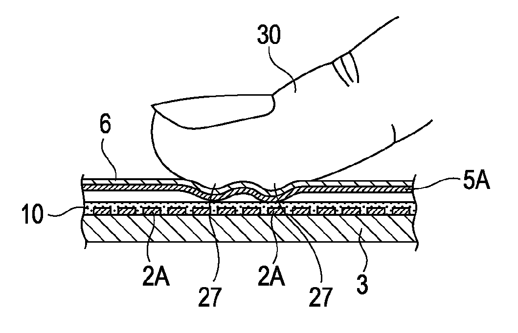
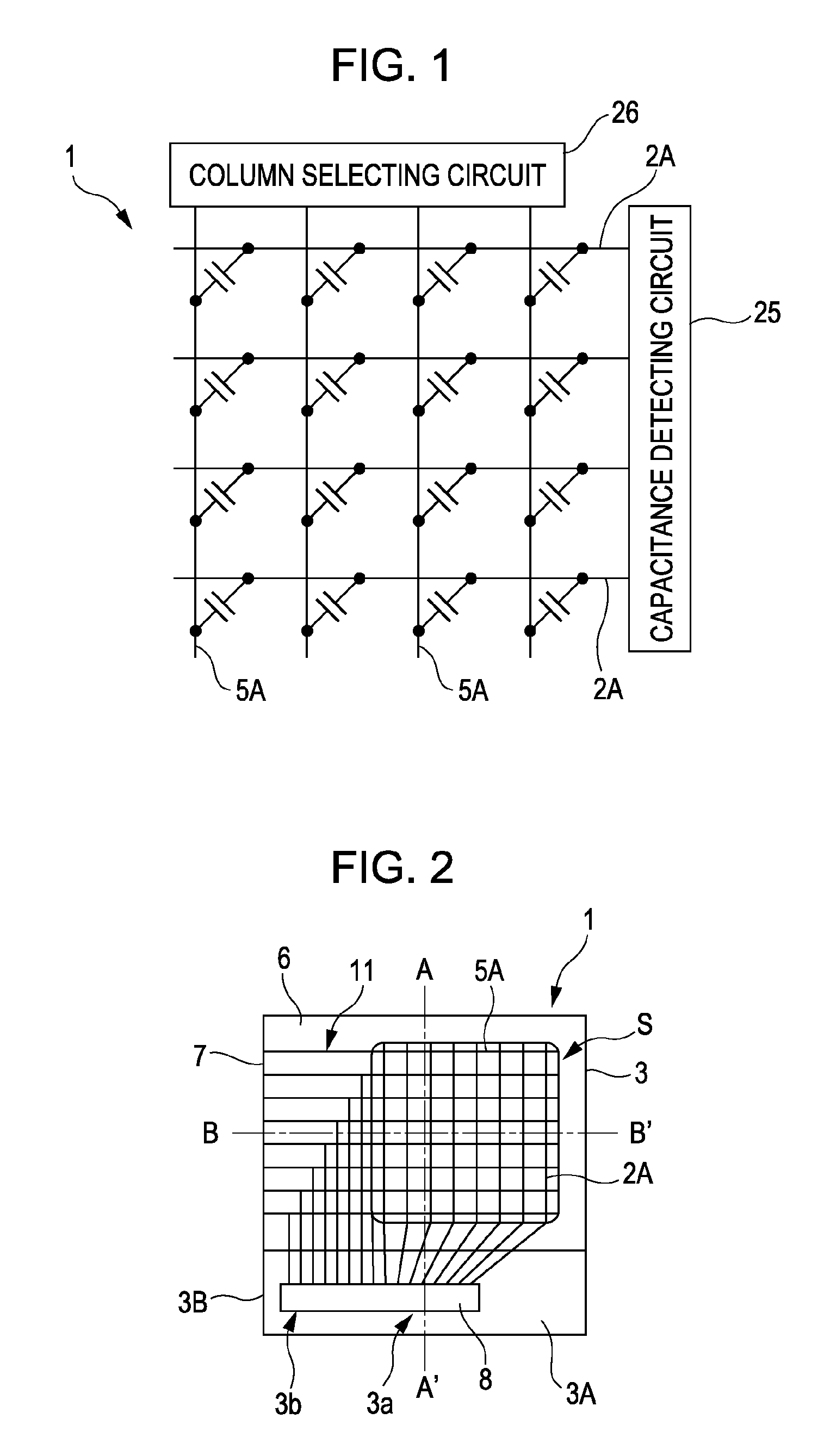
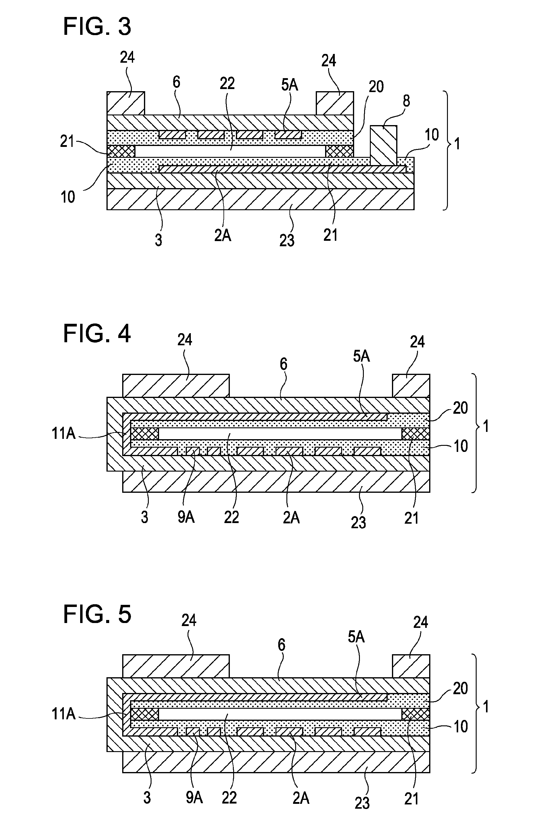
[0024]FIG. 1 is an illustration of an equivalent circuit of a surface pressure distribution sensor according to this embodiment, FIG. 2 is a developed view of a specific configuration of the surface pressure distribution sensor before assembly, FIG. 3 illustrates a plan configuration of the surface pressure distribution sensor after assembly, FIG. 4 is a cross-sectional view taken along the line A-A′ of the surface pressure distribution sensor illustrated in FIG. 3, and FIG. 5 is a cross-sectional view taken along the line B-B′ of the surface pressure distribution sensor illustrated in FIG. 3.

[0025] The surface pressure distribution sensor 1 according to this embodiment has a developed configuration in which a first sub...


PUM


Abstract

[Object] An object of the present invention is to provide a surface pressure distribution sensor capable of maintaining high reliability of lines in a configuration having a folded portion, precisely and stably detecting a surface pressure distribution, and being manufactured with a simple configuration and at low cost. [Solving Means] In the present invention, a first lead line group is placed adjacent to a first line group on a first substrate, a second lead line group connected to a second line group is placed on a second substrate, the second lead line group extends over a boundary portion and connects to the first lead line group on the first substrate, the width of conductors of the first lead line group is smaller than the width of conductors of the first line group and the width of conductors of the second line group, and the width of conductors of the second lead line group positioned in a folded portion of the boundary portion is larger than the width of the conductors of the first lead lined group.

Description

CROSS REFERENCE TO RELATED APPLICATION [0001] This is a continuation of International Application No. PCT / JP2006 / 312100 filed Jun. 16, 2006, which is incorporated herein by reference in its entirety.TECHNICAL FIELD [0002] The present invention relates to a surface pressure distribution sensor to measure fine concavities and convexities of an object. BACKGROUND ART [0003] A surface pressure distribution sensor to detect fine concavities and convexities on a surface of an object pressed onto a detecting surface as distribution of pressing forces has been widely known as a sensor to transform a shape of a rough surface into data (e.g., see Patent Document 1). [0004] In this known type of surface pressure distribution sensor, as illustrated in FIG. 8, semiconductor switching elements 101 are placed in a matrix pattern on a substrate, and electrodes 102 connect to one of terminals of the respective semiconductor switching elements 101. On the opposed plane of the semiconductor substrate,...

Claims


Application Information

Patent Timeline
IPC IPC(8): H01L29/84
CPCG01D5/2417G06K9/0002G01L1/146G01L1/144G06V40/1306
Inventor NAKAMURA, MASAHITO
Owner ALPS ALPINE CO LTD
Learn More