Tamper respondent sensor and enclosure

a technology of respondent and enclosure, which is applied in the direction of burglar alarm mechanical actuation, burglar alarm by hand-portable object removal, instruments, etc., can solve the problems of difficult manufacturing, difficult to penetrate the film without cutting a line, or either on one sid

Inactive Publication Date: 2008-05-08
WL GORE & ASSOC INC
View PDF18 Cites 40 Cited by
  • Summary
  • Abstract
  • Description
  • Claims
  • Application Information

AI Technical Summary

Problems solved by technology

In this manner, complete coverage of the film is obtained, and it is more difficult to penetrate the film without cutting a line, either on one side of the film or the other.
Although these devices are effective, they are difficult to manufacture.

Method used


Image

  • Tamper respondent sensor and enclosure
  • Tamper respondent sensor and enclosure
  • Tamper respondent sensor and enclosure

Examples


Embodiment Construction

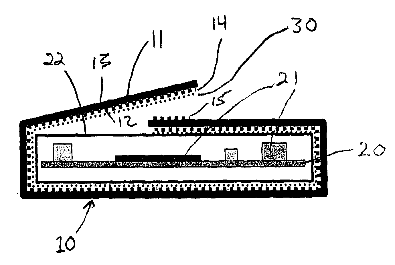
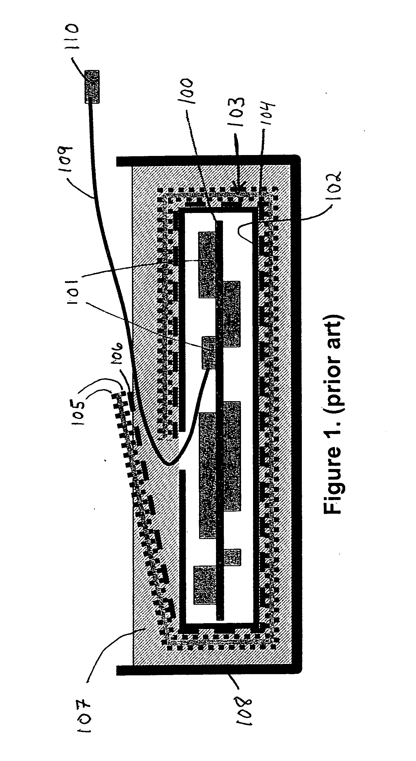
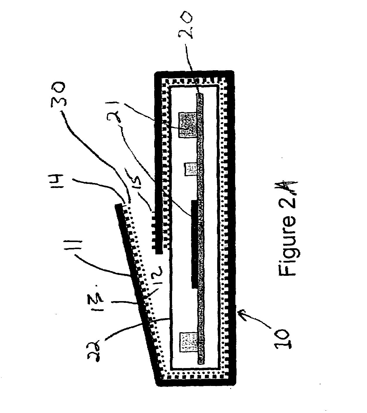
[0020]FIG. 1 is a schematic diagram of a prior art tamper respondent enclosure. Circuit board 100 has components 101 disposed thereon. Components 101 contain the sensitive information that is desired to be protected. A box or enclosure 102 surrounds circuit board 100 and components 101. Enclosure 102 has a sensor 103 disposed around it. Sensor 103 comprises a clear PET substrate 104. On both sides of PET substrate 104 are disposed printed traces 105. This is a matrix of conductive lines on each side. The lines are disposed in offsetting relation from one side to the other to ensure complete coverage of PET substrate 104. The inside of PET substrate 104 also has a layer of adhesive 106 disposed over the printed trace 105 on that surface. Adhesive layer 106 is a pressure sensitive adhesive (PSA). In this prior art device, the entire sensor is then encapsulated in an opaque encapsulant or potting material 107. Potting material 107 helps obfuscate printed traces 105. An outer shell 108 ...


PUM


Abstract

A tamper respondent enclosure including (a) a circuit board; (b) an enclosure surrounding the circuit board; (c) a tamper respondent sensor having (i) a substrate with first and second sides; (ii) a first layer of conductive traces on the first side; (d) wherein the tamper respondent sensor is wrapped around the enclosure with at least one overlap region; and (e) wherein only at the at least one overlap region the tamper respondent sensor has a second layer of conductive traces on the second side. Preferably, the substrate is insulating and made of opaque PET, and the first layer is adjacent the enclosure.

Description

FIELD OF THE INVENTION[0001]This invention relates to tamper respondent enclosures, and in particular, to a sensor used as a tamper respondent enclosure.BACKGROUND OF THE INVENTION[0002]Tamper respondent enclosures are used in various applications, including the transport of sensitive information and protecting electronic devices. Typical enclosures are in the form of envelopes and shallow boxes, the walls of which are formed by folding flexible sheets incorporating tamper detection features. As used herein, sheets incorporating tamper detection features are known as “sensors”. These sheets may also be wrapped around preexisting boxes or enclosures.[0003]Included in such sheets are layers of flexible material and a matrix of diagonally extending or zig-zag pattern semi-conductive or conductive lines, also known as conductive traces. The lines or traces are printed on thin insulating film. The matrix of lines forms a continuous conductor which is broken if attempts are made to penetr...

Claims


Application Information

Patent Timeline
Patent Type & Authority Applications(United States)
IPC IPC(8): G08B21/00
CPCG06F21/87G06F2221/2101G08B13/128H05K2201/10151H05K1/0393H05K2201/056H05K1/0275
Inventor HUNTER, STEVE B.VOLTZ, JOHN A.LEWIS, BRENT W.WYLIE, HAROLD S.
Owner WL GORE & ASSOC INC
Why Eureka
Try Eureka