
Multi-Function Sensor

a multi-functional, sensor technology, applied in the direction of instruments, heat measurement, specific gravity measurement, etc., can solve the problem that the devices have not combined multiple functionalities into a single sensor device, and achieve compact and simple design, and the effect of low cos

Inactive Publication Date: 2008-05-08
THERM O DISC
View PDF13 Cites 79 Cited by
  • Summary
  • Abstract
  • Description
  • Claims
  • Application Information

AI Technical Summary

Benefits of technology

[0006]The invention provides an extremely reliable multi-function sensor which is compact and simple in design and can be manufactured at very low costs. Further the sensor of the invention can be encapsulated or coated with a variety of suitable materials to enable it to maintain prolonged operation in numerous different and potentially hostile ambient environments.
[0012]The arrangement of the multi-function sensor of the invention not only provides a very simple and reliable device for obtaining measurements for multiple ambient conditions in an environment, but also further minimizes the number of mounting locations on a container and the corresponding penetrations extending through the container wall. This feature is significant, particularly when the sensor is to be employed within a closed or sealed system.

Problems solved by technology

Such sensor devices, however, have not combined the multiple functionalities into a single sensor device.

Method used


Image

  • Multi-Function Sensor
  • Multi-Function Sensor
  • Multi-Function Sensor

Examples


Embodiment Construction

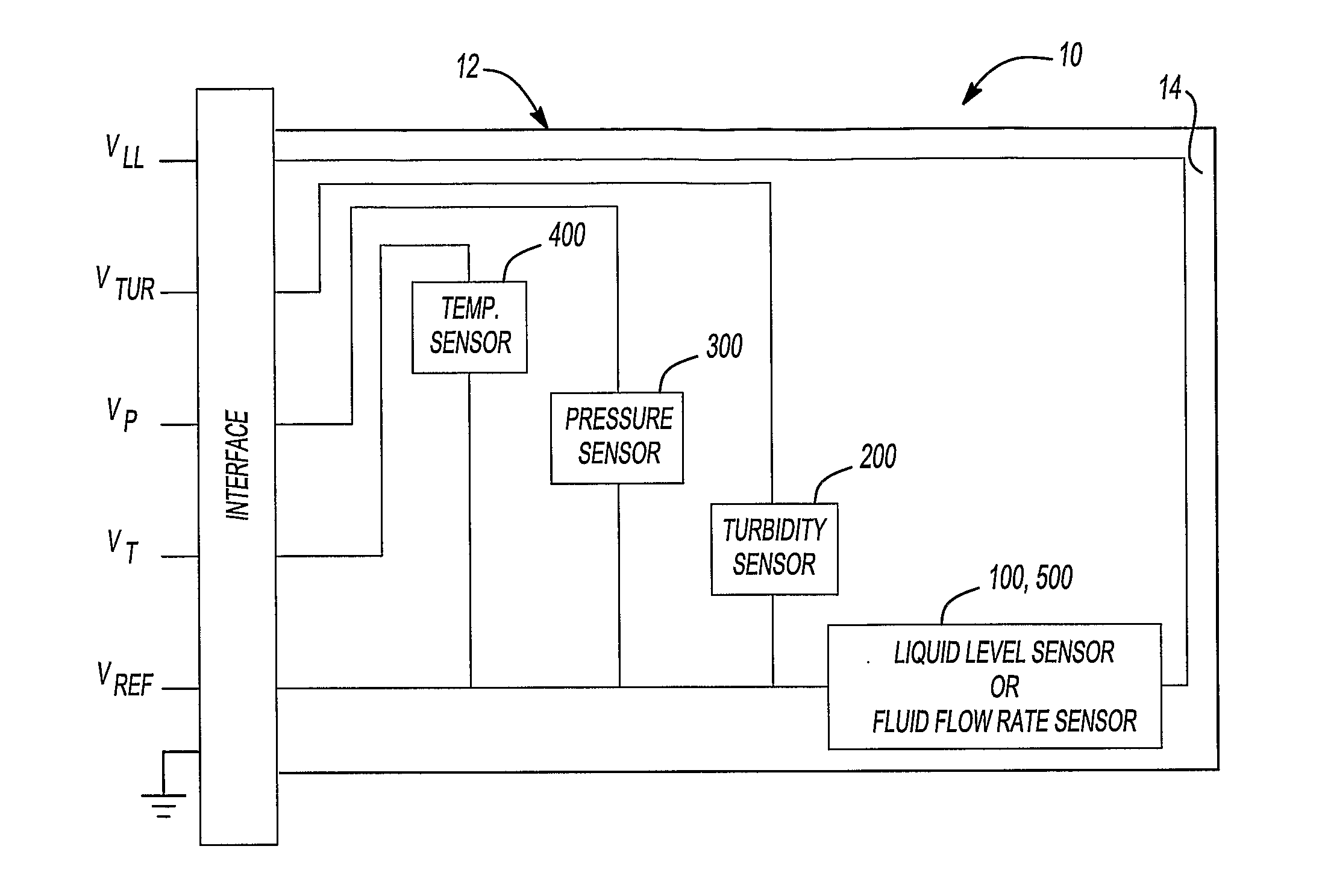
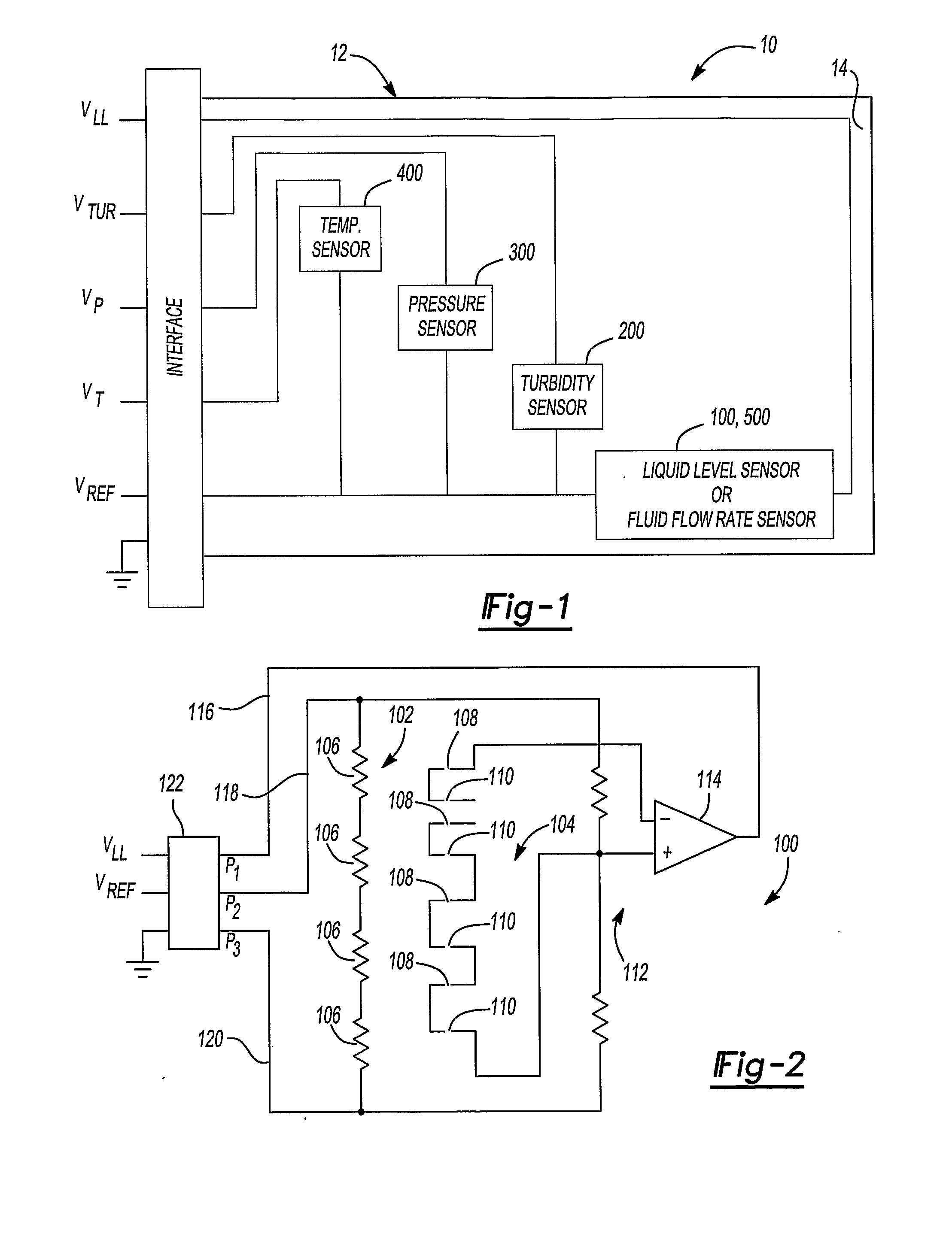
[0036]Referring now to the drawings and in particular to FIG. 1, there is shown a schematic block diagram of a multi-function sensor 10 in accordance with the invention. Multi-function sensor 10 comprises a printed circuit board 12 upon which a plurality of sensor modules 100 or 200, 300, 400, and 500 are supported. The sensor modules 100 or 200, 300, 400, and 500 may include a liquid level sensor module 100, a turbidity sensor module 200, a pressure sensor module 300 and a temperature sensor module 400 Alternatively to the liquid level sensor 100, a fluid flow rate sensor module 500 may be incorporated into the multi-function sensor 10. Although FIG. 1 schematically depicts the several sensor modules 100, 200, 300, 400, 500 in a particular combination, it is understood that any combination of the several sensor modules 100, 200, 300, 400, 500 may be employed to provide a multi-function sensor in accordance with the invention.

[0037]The printed circuit board 12 includes a relatively ...


PUM


Abstract

A multi-function sensor is disclosed for measuring the conditions within a container, such as fluid level, turbidity, temperature and pressure. The sensor incorporates a fluid level sensor module, a turbidity sensor module, a temperature sensor module and a pressure sensor module. The fluid level sensor module utilizes a plurality of thermocouple junctions grouped in pairs with the pairs being spaced along a line extending generally in the direction in which the liquid level may vary. The thermocouple junctions are connected in series and produce a signal indicative of the level along the sensor. Turbidity, temperature, and pressure sensor modules may also be incorporated in the multi-function sensor. Alternatively, a fluid flow rate sensor module may be included in place of the liquid level sensor module.

Description

CROSS-REFERENCE TO RELATED APPLICATIONS[0001]This application claims the benefit of U.S. Provisional Application No. 60 / 564,129, filed on Apr. 21, 2004. The disclosure of the above application is incorporated herein by reference.FIELD OF THE INVENTION[0002]The invention relates generally to devices used to measure certain ambient conditions within an environment, such as the level or flow rate of a fluid or within a vessel or container, the turbidity of the fluid, and the temperature or pressure of the fluid and / or the ambient environment.BACKGROUND OF THE INVENTION[0003]There exists a wide variety of applications in which it is desirable to measure and / or monitor to some degree certain ambient conditions within a container or the like, such as the level of a fluid, the flow rate of a fluid, the turbidity of a fluid, the temperature of a fluid or its surrounding environment and the ambient pressure. Such applications may range from monitoring these conditions in various systems, suc...

Claims


Application Information

Patent Timeline
IPC IPC(8): G01K1/08G01F1/696G01F23/20G01F23/22G01F23/24
CPCG01F1/696G01F23/248G01F23/247G01F23/22
Inventor KHADKIKAR, PRASADZIMMERMANN, BERND D.
Owner THERM O DISC
Learn More