X-Ray Ct Apparatus

a technology of ct apparatus and x-ray, which is applied in the direction of tomography, material analysis using wave/particle radiation, instruments, etc., can solve the problems of unsolved, reduced quality of tomographic images at parts of objects containing many bones, etc., and achieves high quality

Inactive Publication Date: 2008-05-08
HITACHI LTD
View PDF20 Cites 42 Cited by
  • Summary
  • Abstract
  • Description
  • Claims
  • Application Information

AI Technical Summary

Benefits of technology

[0009] According to the present invention, tomographic images of high quality can be obtai

Problems solved by technology

However, the conventional art is confined to the setting of the X-ray tube current control values based on the prepared scanogram and does not take in to account a fact that X-ray absorption amount in scanogram differs depending on respective tissues of the object such as bones where X-ray attenu

Method used


Image

  • X-Ray Ct Apparatus
  • X-Ray Ct Apparatus
  • X-Ray Ct Apparatus

Examples


Embodiment Construction

[0019] Herein below, an embodiment of an X-ray CT apparatus according to the present invention will be explained with reference to the accompanied drawings. An X-ray CT apparatus 1 according to the present embodiment measures projection data of a object while controlling X-ray tube current depending on an X-ray tube position (θ, Z). Further, in all of the drawings for explaining the embodiment of the present invention, ones having the same functions are designated with the same reference numerals and repetitive explanation thereof is omitted.

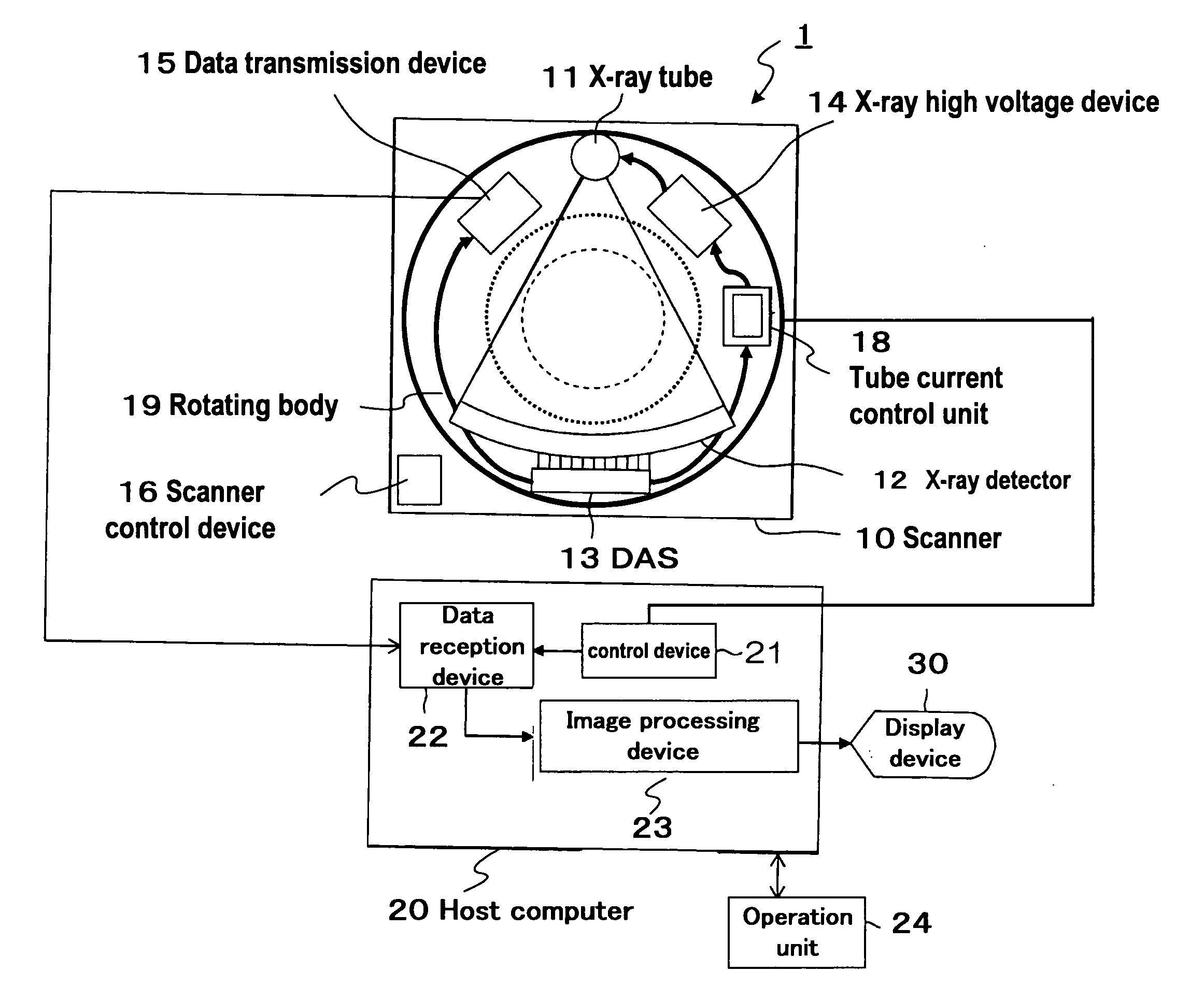
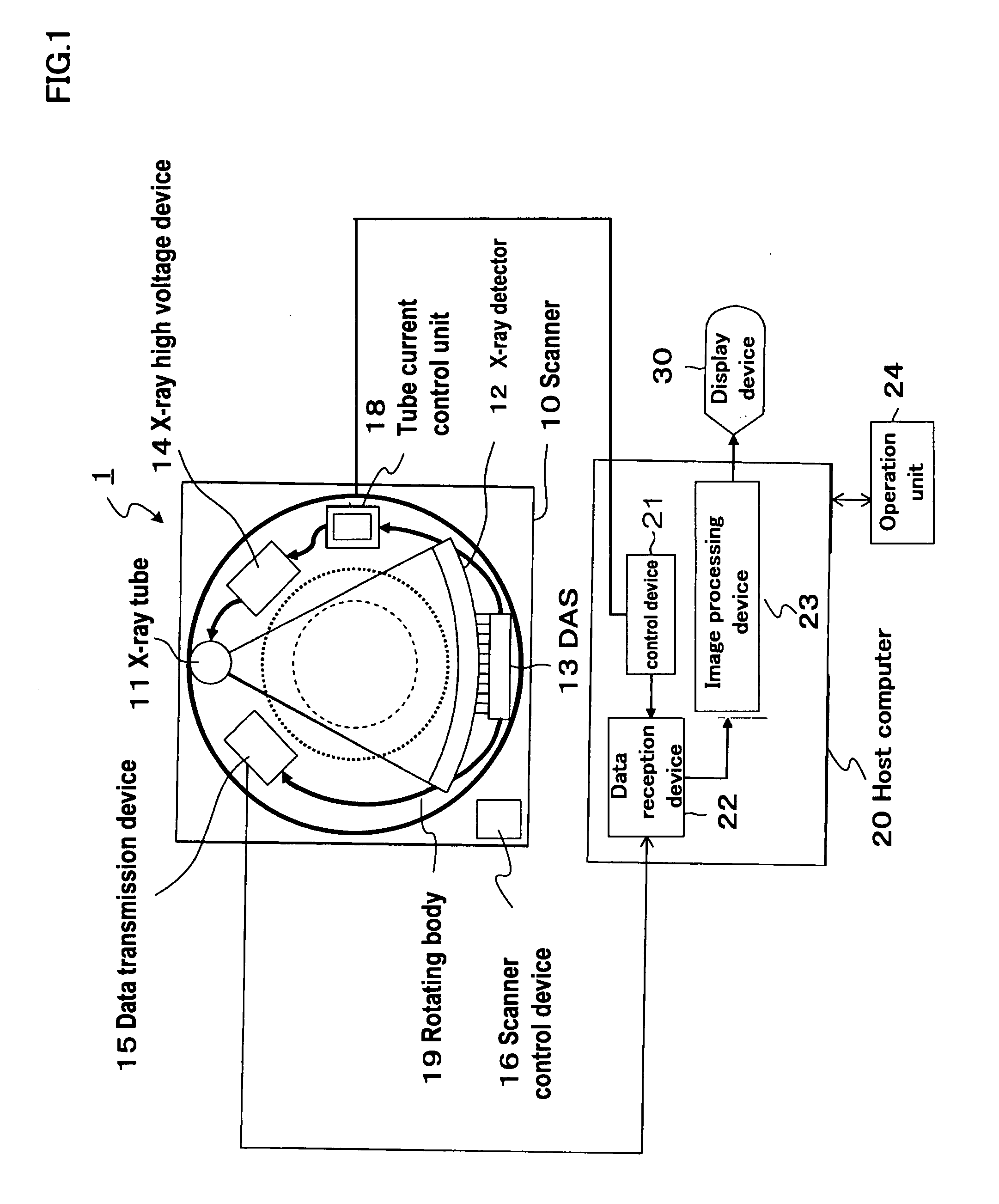
[0020]FIG. 1 shows a constitution of the X-ray CT apparatus 1 according to the present embodiment. The X-ray CT apparatus 1 is constituted by a scanner 10, a host computer 20 connected to the scanner 10, an operation unit 24 connected to the host computer 20 and a display unit 30.

[0021] At first the constitutional elements of the scanner 10 will be explained.

[0022] An X-ray tube 11 irradiates X-rays to an object. An X-ray detector 12 is dispo...


PUM


Abstract

In an X-ray CT apparatus comprising an X-ray source irradiating X-rays to an object, an X-ray detector that is disposed oppositely to the X-ray source in a manner placing the object therebetween and is to detect transmitting X-rays through the object as projection data, a rotating means that rotates the X-ray source and the X-ray detector, a control means that collects the projection data from plural angular directions obtained through rotation of the X-ray tube and the X-ray detector by the rotating means, performs reconstruction computation of these collected projection data to produce tomographic images of the object as well as controls the X-ray source and the rotating means and a display means that displays the produced tomographic images, the X-ray CT apparatus further comprising a projection data analysis means that reconstructs a tomographic image at an imaging portion of the object used for analysis from the projection data and produces a control profile by reprojecting the reconstructed tomographic image and a tube current control means that controls value of current to be fed to the X-ray tube based on the produced control profile.

Description

FIELD OF THE INVENTION [0001] The present invention relates to an improvement in an X-ray CT apparatus that permits to control X-ray source current (herein after will be called as X-ray tube current) fed to an X-ray source (herein after will be called as X-ray tube) which determines X-ray irradiation density to an imaging region of an object to be examined depending on positions in body axial direction of the object. [0002] The present application is an application claiming Paris Convention priority based on Japanese Patent Application No. 2005-051497 under Japanese Patent Law and is an application, which enjoys the benefit of Japanese Patent Application No. 2005-051497 by reference. CONVENTIONAL ART [0003] Quality of images obtained by an X-ray CT apparatus is determined by factors such as spatial resolution and noises contained in the images. Among these factors, the image noises primarily depend on the intensity of transmitting X-rays. The intensity of transmitting X-rays is dete...

Claims


Application Information

Patent Timeline
IPC IPC(8): G01N23/00G06K9/00
CPCA61B6/542A61B6/032
Inventor MIYAZAKI, OSAMUHIROKAWA, KOICHIIRIE, TOSHIYUKI
Owner HITACHI LTD
Why Eureka
Try Eureka