Portable wireless terminal for visible light communication

a wireless terminal and wireless terminal technology, applied in the field of portable wireless terminals, can solve the problems of difficult to establish interactive communication, limited available time, and large amount of power, and achieve the effect of facilitating communication and facilitating communication

Inactive Publication Date: 2008-05-08
SAMSUNG ELECTRONICS CO LTD
View PDF12 Cites 40 Cited by
  • Summary
  • Abstract
  • Description
  • Claims
  • Application Information

AI Technical Summary

Benefits of technology

[0009]Accordingly, the present invention has been made to solve the above-mentioned problems occurring in the prior art and provides additional advantages, by providing a portable wireless terminal for performing visible light communication with other devices, even without a light source.

Problems solved by technology

However, in a visible light communication system as described above, one wireless terminal may be under conditions (e.g. power, a light source, etc.) sufficient for transmission of visible light signals whereas the other wireless terminal may be under insufficient conditions thereof.
If so, it is difficult to establish interactive communication.
In order to generate visible light signals, a lot of power is required.
Therefore, these conditions may emerge as a big problem in terms of the portable wireless terminal featuring a limited available time.

Method used


Image

  • Portable wireless terminal for visible light communication
  • Portable wireless terminal for visible light communication
  • Portable wireless terminal for visible light communication

Examples


first embodiment

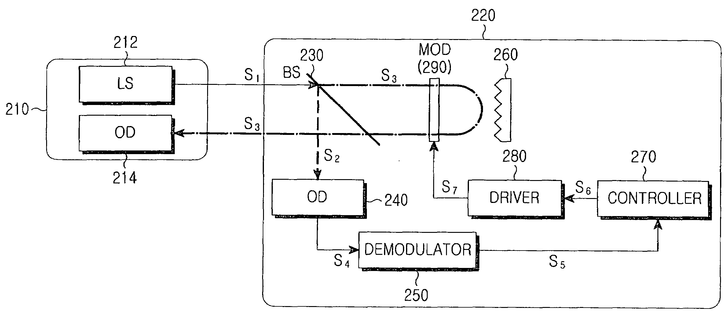
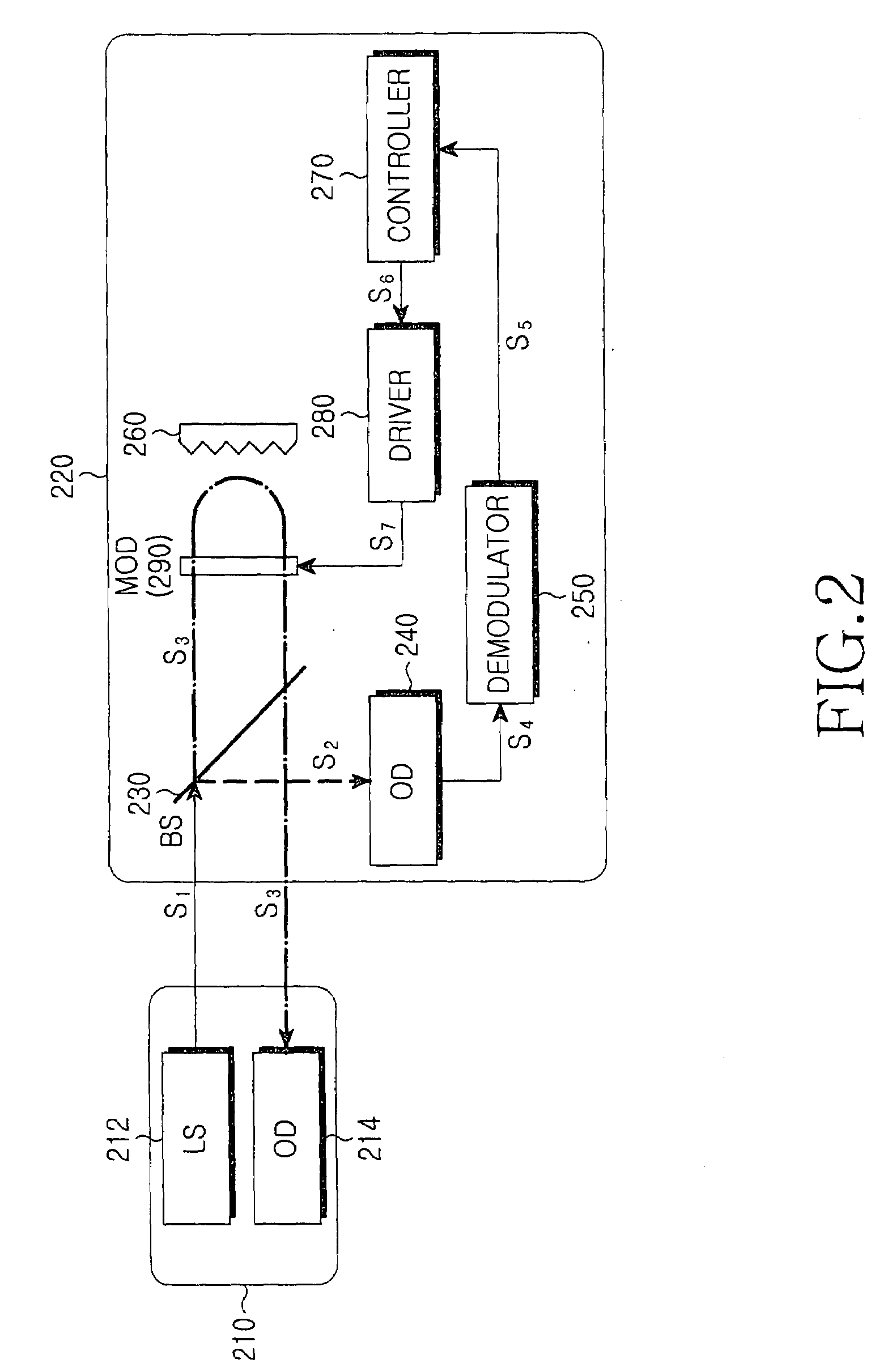
[0018]FIG. 2 is a block diagram illustrating a visible light communication system including a portable wireless terminal according to the present invention, and FIG. 3 is a sectional view illustrating of a reflector shown in FIG. 2.

[0019]Referring to FIG. 2, the visible light communication system 200 includes a fixed wireless terminal 210 and a portable wireless terminal 220 for individually transmitting / receiving optical signals through free space.

[0020]The fixed wireless terminal 210 includes a light source 212 for generating a data-modulated optical signal S1 and outputting the generated optical signal S1 to the portable wireless terminal 220, and the optical detector 214 for photoelectrically converting an optical signal S3 input from the portable wireless terminal 220 into an electrical signal. The fixed wireless terminal 210 demodulates a data signal from the electrical signal output from the optical detector 214.

[0021]The portable wireless terminal 220 includes a Beam Splitte...

second embodiment

[0030]the present invention provides a reflector capable of significantly increasing an allowed angle of retro-reflection and the reflector may be replaced with the reflector 260 shown in FIG. 2.

[0031]FIG. 5 is a sectional view illustrating a reflector according to a second embodiment of the present invention. As shown, the reflector 400 substantially has a shape of a rectangular plate, and has a reflection surface 410 for reflecting an incident optical signal back in a direction opposite to the incident direction. The reflection surface 410 has at least one concave groove 420 formed thereon and the concave groove 420 has a hierarchical structure including a plurality of stairs.

[0032]The concave groove 420 has a bottom surface 422 and a plurality of stairs 424, which are formed symmetrically with respect to the bottom surface 422 and are formed through repeated 90° upward bending from the bottom surface 422. For example, in order to implement the reflector 400, grooves having decrea...


PUM


Abstract

A portable wireless terminal for performing visible light communication with other devices through free space includes an optical detector for generating an electrical signal after photoelectrically converting some of optical signal input from free space and outputting the electrical signal; a reflector for retro-reflecting the others of the optical signal incident on the concave grooves, the reflector having a reflection surface on which at least one concave groove is formed; and a modulator for outputting the retro-reflected optical signal after data modulation.

Description

CLAIM OF PRIORITY[0001]This application claims the benefit under 35 U.S.C. §119(a) of an application entitled “Portable Wireless Terminal for Visible Light Communication,” filed in the Korean Intellectual Property Office on Nov. 7, 2006 and assigned Serial No. 2006-109397, the contents of which are hereby incorporated by reference.BACKGROUND OF THE INVENTION[0002]1. Field of the Invention[0003]The present invention relates to a portable wireless terminal. More particularly, the present invention relates to a portable wireless terminal for performing visible light communication with other devices through free space.[0004]2. Description of the Related Art[0005]Visible light communication is based on the fact that the wireless terminal of a transmission end transmits data-modulated visible light signals to the wireless terminal of a reception end, then the wireless reception terminal demodulates data signals from the received visible light signals. In the visible light communication, t...

Claims


Application Information

Patent Timeline
Patent Type & Authority Applications(United States)
IPC IPC(8): H04B10/00
CPCH04B10/1143H04B10/2587H04B10/116G02B5/12H04B10/40
Inventor WON, EUN-TAE
Owner SAMSUNG ELECTRONICS CO LTD
Why Eureka
Try Eureka