Fan device capable of increasing air pressure and air supply

Inactive Publication Date: 2008-05-08
CHANG BOR HAW +2
View PDF13 Cites 10 Cited by
  • Summary
  • Abstract
  • Description
  • Claims
  • Application Information

AI Technical Summary

Benefits of technology

[0009]another object of the present invention is to provide a fan device capable of increasing air pressure and air supply in which the concave inward curved surface is capable of gathering the air flow and increasing air pressure for decreasing noise.
[0010]In order to achieve the preceding object, a fan device capable of increasing air pressure and air supply according to the present invention includes a fan frame, a base and a fan wheel. The fan frame has an air inlet side, an air outlet and a flow path which defined by the inner wall of the frame. The base is disposed in the flow path and joined to the inner wall of the fan fram

Problems solved by technology

However, a problem of the preceding prior art is in that the air outward port of the guide flow device has a fixed area to limit amount of air flow such that only a certain area of the heat sink can perform heat exchange with the air flow.
Another problem of the

Method used


Image

  • Fan device capable of increasing air pressure and air supply
  • Fan device capable of increasing air pressure and air supply
  • Fan device capable of increasing air pressure and air supply

Examples


Example

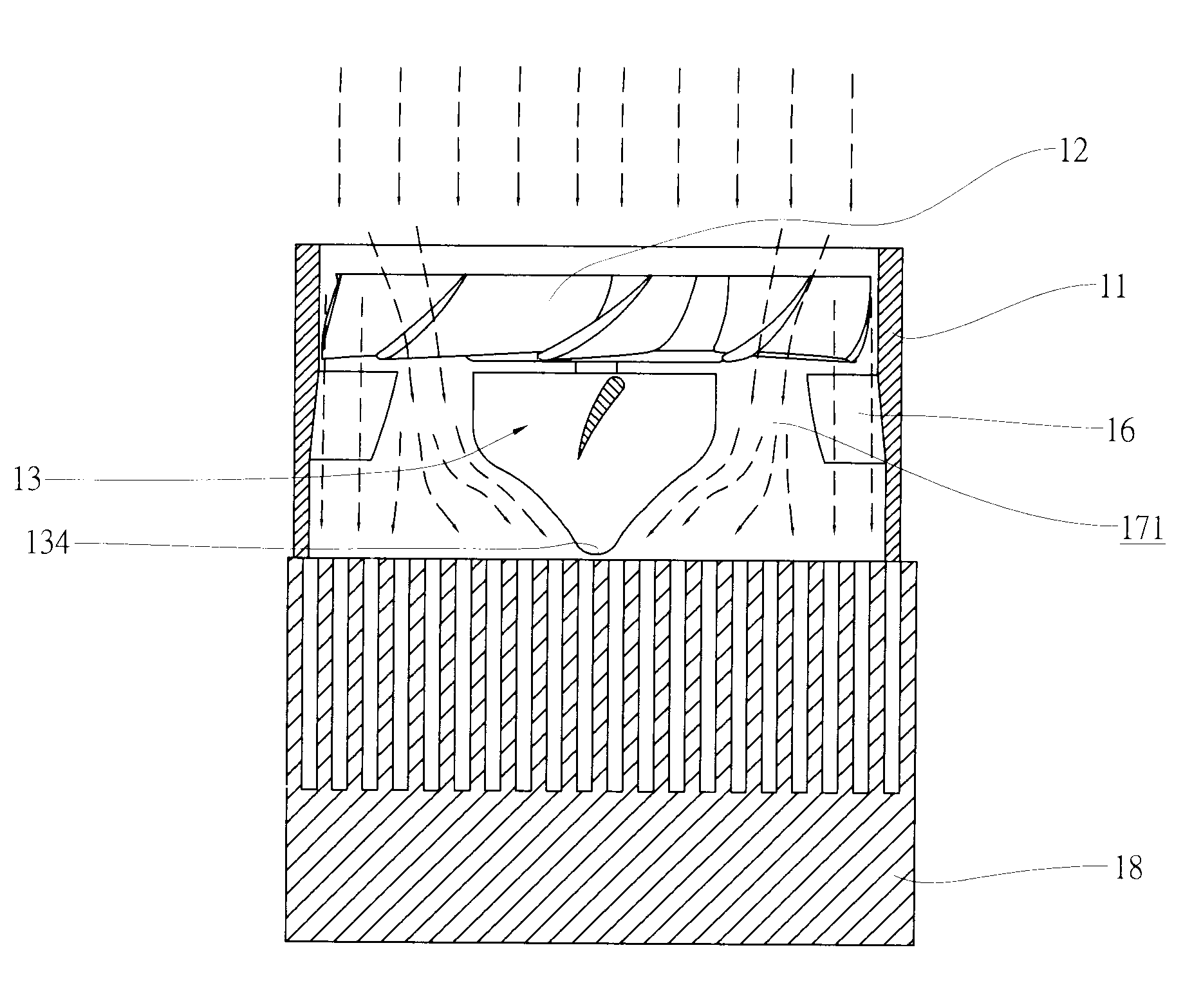
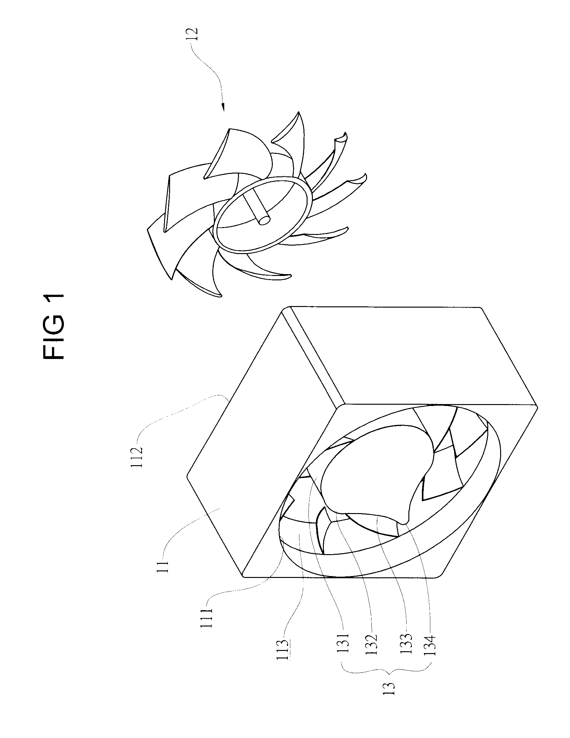
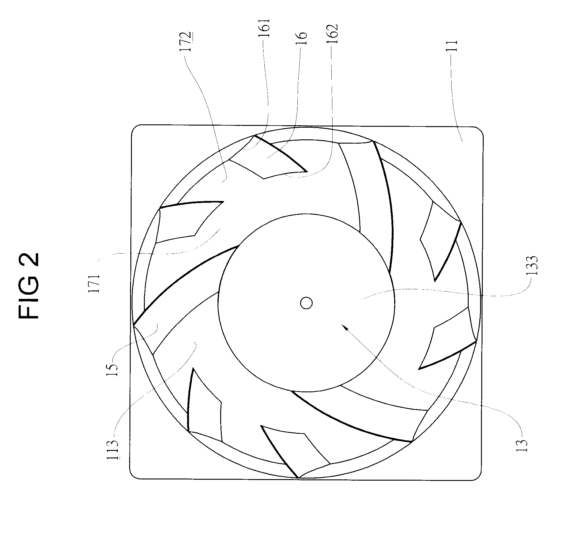
[0017]Referring to FIGS. 1, to 3, a fan device according to the present invention includes a fan frame 11 and a fan wheel 12. The fan frame 11 has an outlet side 111, an inlet side 112 and a flow path 113 communicating the inlet side 111 and the outlet side 112. Further, a base 13 is disposed in the flow path 113. The base 13 includes a main base part 131 and a shoulder part 132. It can be seen in FIG. 3, The shoulder part 132 has a streamline contour extending from a lateral side of the main base part 131 to the inlet side 111 of the fan frame 11 and provides a concave inward curved surface 133 converging toward the central axis 14 such that a tip end 134 is formed at the central axis 14.

[0018]Referring to FIG. 2 again, the base 13 is joined to the inner wall of the fan frame 11 with a plurality of elongated fan blade shaped connecting parts 15 such that the base 13 is held in the flow path 113.

[0019]Referring to FIG. 4, the fan wheel 12 is rotatably to the base main part 131 oppos...


PUM


Abstract

A fan device capable of increasing air pressure and air supply includes a fan frame, a base and a fan wheel. The fan frame has an air inlet side, an air outlet and a flow path which defined by the inner wall of the frame. The base is disposed in the flow path and joined to the inner wall of the fan frame by means of a plurality of elongated fan blade shaped connecting parts being attached to the inner wall of the frame. The fan wheel is movably attached to the base from the air inlet side. The base further includes a main base part and a shoulder part with a streamline contour extending from a lateral side of the main base part to approach the air outlet side of the fan frame such that a concave inward curved surface converging toward a central axis of the base is formed with a tip end is disposed at the central axis to concentrate fluid flow and increase air pressure for eliminating stagnation zone and promoting heat dissipation.

Description

BACKGROUND OF THE INVENTION[0001]1. Field of the Invention[0002]The present invention is related to a fan device and particularly to a fan device capable of increasing air pressure and air supply for eliminating stagnation zone behind the base of the fan device.[0003]2. Brief Description of the Related Art[0004]Normally, the conventional fan includes a fan wheel and a fan frame. The fan frame has a base for being rotatably attached with the fan wheel, an air inlet and an outlet. The air outlet is disposed corresponding to a heat generating component and the fan frame is attached to the heat generating component with at least a fastening element. Due to the base having a flat shape area, a low pressure zone is constituted behind the base. When air flows outward the fan frame via the outlet, air flows back at the low pressure zone instead of moving to the heat generating component to decrease heat dissipation efficiency tremendously.[0005]In order to overcome the preceding deficiency,...

Claims


Application Information

Patent Timeline
IPC IPC(8): F04D29/52F04D3/00
CPCF04D25/082F04D29/545F04D29/541F04D29/5806
Inventor CHANG, BOR-HAWLIU, WEN-HAOHUANG, CHIA-LIEH
Owner CHANG BOR HAW
Why Eureka
Try Eureka