Rotary Compressor

a compressor and rotary technology, applied in the direction of positive displacement liquid engines, piston pumps, liquid fuel engines, etc., can solve the problems of increasing the rotational speed of the reciprocating compressor, reducing the compression efficiency of the compressor, so as to achieve the compression efficiency with accuracy and reduce the compression efficiency

Active Publication Date: 2008-05-08
LG ELECTRONICS INC
View PDF2 Cites 12 Cited by
  • Summary
  • Abstract
  • Description
  • Claims
  • Application Information

AI Technical Summary

Benefits of technology

[0011]Another object of the present invention is to provide a rotary compressor in which oil inflow into the compression chamber is in advance cut off to prevent the compression efficiency from being lowered.
[0012]A fur

Problems solved by technology

However, the reciprocation compressor has a limitation in increasing its rotational speed due to the inertia of the piston and a disadvantage in that a considerable vibration occurs due to the inertial force.
However, in spite of the aforementioned advantages, the rotary compressor has a structural limitation

Method used


Image

  • Rotary Compressor
  • Rotary Compressor
  • Rotary Compressor

Examples


first embodiment

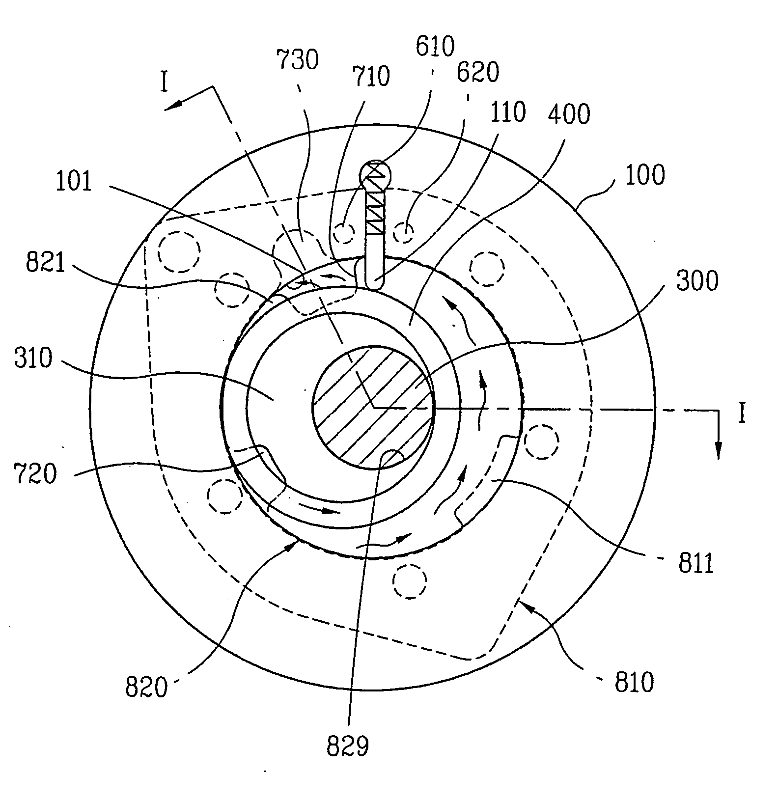
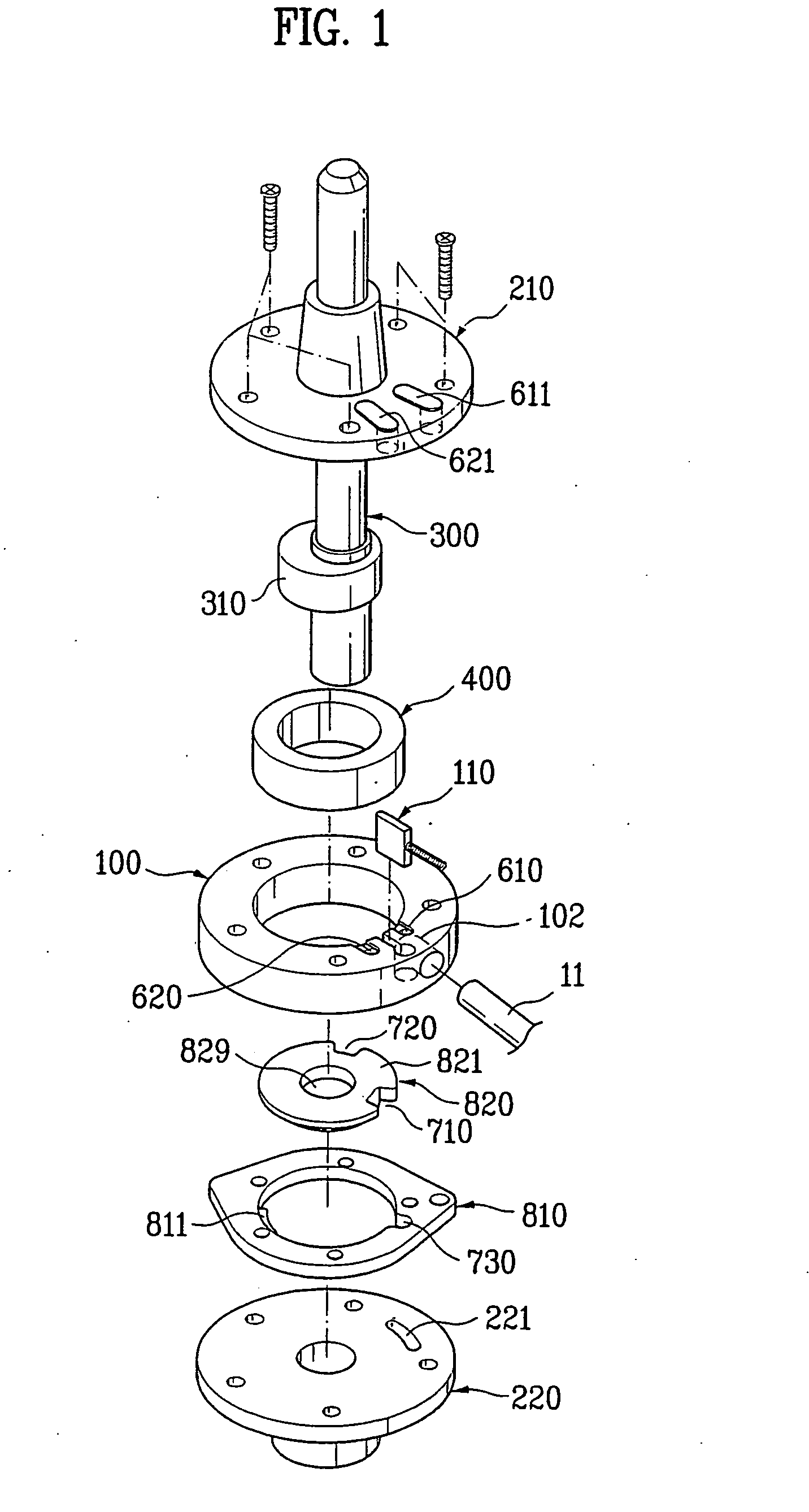
[0041]Referring first to FIG. 1, a compressor of the present invention includes a cylinder 100, an upper bearing 100, a lower bearing 210, a crankshaft 300, a roller 400, a discharge port and a valve assembly.

[0042]The cylinder 100 is provided therein with an inner space. A vane 110 is elastically mounted on an inner circumference of the cylinder 100 defining the inner space, so as to be protruded inwardly. The vane 110 always contacts an outer circumference of the roller 400 and thereby it is configured to divide the inner space of the cylinder 100 into a refrigerant compression section and a refrigerant suction section.

[0043]The upper and lower bearings 210 and 220 are respectively disposed above and below the cylinder 100 to define a compression chamber by sealing the inner space, while supporting the crankshaft 300.

[0044]The discharge port includes first and second discharge ports 610 and 620, and is configured to penetrate the upper bearing 210 from the upper side of the cylind...

second embodiment

[0090]Therefore, in the present invention, a second suction port 720 disposed out of the compression chamber 101 is proposed.

[0091]In other words, the second embodiment provides a valve assembly having a central axis, which is eccentric with respect to a central axis of the crankshaft 300. The second embodiment will be described in more detail with reference to FIGS. 8 to 12b.

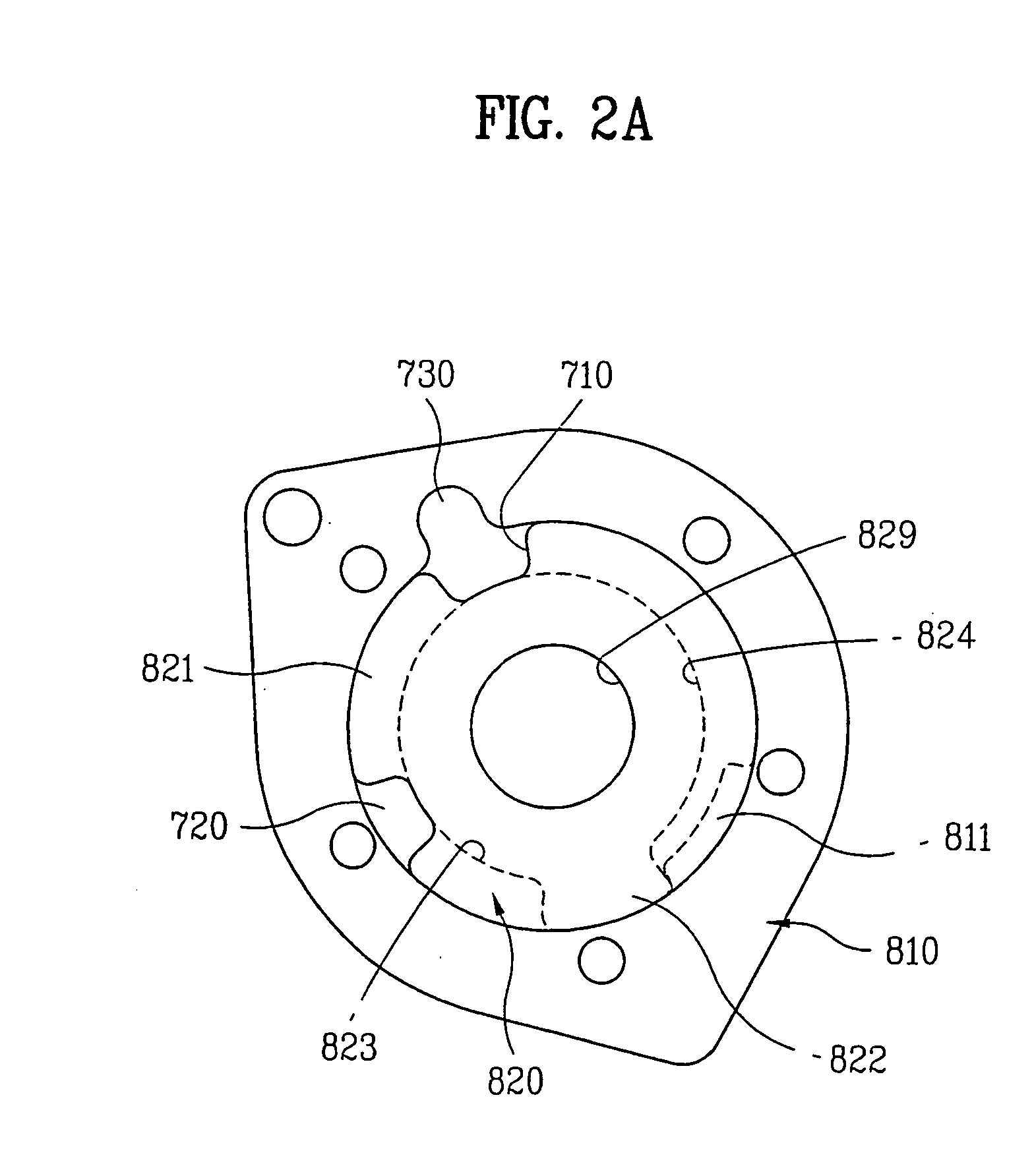
[0092]The valve assembly of this embodiment comprises rotational and stationary valves 820 and 810 that are similar to those of the first embodiment.

[0093]In other words, the rotational valve 820 is provided with first and second suction ports 710 and 720, first and second stoppers 821 and 82′, first and second fluid flowing portions 823 and 824, and a hook step 811.

[0094]The rotational valve 820 is further provided with a penetration hole 829 having a diameter greater than that of the crankshaft 300 by an eccentric distance of the valve assembly. The greater diameter of the penetration hole 829 enables the cr...

third embodiment

[0126]In the third embodiment, as shown in FIGS. 13 to 14B, a refrigerant storing portion 500 for storing the refrigerant fed from the outside and supplying the stored refrigerant to the valve assembly is further provided under the lower bearing 220.

[0127]The valve assembly of this embodiment comprises rotational and stationary valves 820 and 810 that are identical to those of the second embodiment.

[0128]The refrigerant storing portion 500 is connected to an outer refrigerant storing container such as an accumulator by a refrigerant tube 11. The lower bearing 220 is provided with at least one second communication hole 222 communicating with an inner space of the refrigerant storing portion 500.

[0129]The second communication hole 222 is formed corresponding to the third suction port 730 of the stationary valve 810.

[0130]It is also possible that the lower bearing 220 is provided with a communication hole (not shown) disposed corresponding to a position where the first suction port 710...


PUM


Abstract

Disclosed is a rotary compressor having two compression capacities according to the two different rotational directions of the driving shaft (300). The rotary compressor includes: a driving shaft (300) with an eccentric portion (310) on which a roller (400) rotates along an inner circumference of the cylinder (100), a vane (110) installed in the cylinder (100) to contact the roller (400) continuously, an upper (210) and one lower (220) bearing respectively disposed on top and bottom of the cylinder (100), a disc shaped valve (820) rotates between two positions and has at least one suction port (710 or 720) for selectively supplying refrigerant inside the compression chamber (100) according to the rotational direction of the driving shaft (300) and at least one discharge port (621 or 611) communicating with the compression chamber (100) for discharging the compressed refrigerant. The refrigerant is supplied through a communication hole (102) to a port (730) formed on the outer valve (810).

Description

TECHNICAL FIELD[0001]The present invention relates to a rotary compressor, and more particularly, to a rotary compressor that can be operated at different compression capacities and enables a precise location change of components every compressive capacity.BACKGROUND ART[0002]In general, compressors are machines that are supplied power from a power generator such as electric motor, turbine or the like and apply compressive work to a working fluid, such as air or refrigerant to elevate the pressure of the working fluid. Such compressors are widely used in a variety of applications, from electric home appliances such as air conditioners, refrigerators and the like to industrial plants.[0003]The compressors are classified into two types according to their compressing methods: a positive displacement compressor, and a dynamic compressor (a turbo compressor).[0004]The positive displacement compressor is widely used in industry fields and configured to increase pressure by reducing its vo...

Claims


Application Information

Patent Timeline
IPC IPC(8): F01C1/063F04C18/356F04C18/00F04C28/04F04C28/14
CPCF04C18/3564F04C2250/101F04C28/14F04C28/04Y10T137/86638F04C18/00
Inventor BAE, JI YOUNGROH, CHUL GIPARK, KYOUNG JUNJANG, CHANG YONGKIM, JONG BONG
Owner LG ELECTRONICS INC
Why Eureka
Try Eureka