
Method, system and apparatus for scraping a roll surface in a molten metal coating process

a technology of molten metal coating and roll surface, which is applied in the direction of pretreatment surfaces, metal material coating processes, coatings, etc., can solve the problems of defective products that fail to meet product specifications, unusable substances known as dross, impurities in the bath, etc., and achieve the effect of minimalism of weigh

Active Publication Date: 2008-05-08
NITED STATES STEEL CORP
View PDF8 Cites 1 Cited by
  • Summary
  • Abstract
  • Description
  • Claims
  • Application Information

AI Technical Summary

Benefits of technology

Enhances dross removal efficiency, reduces production downtime, and ensures consistent coating quality by providing controlled pressure and precise scraping motion, minimizing defects and worker safety risks.

Problems solved by technology

Inter-metallic particles and oxides form in the bath and create undesirable substances known as dross.
The primary causes of dross are impurities in the bath (primarily iron) and temperature differentials between the molten bath, the entering substrate steel, and the sink roll equipment.
Dross can form on the sink roll, causing degradation in the quality of the coated strip metal in the form of dents, resulting in defective product that fails to meet product specifications.
In zinc-aluminum continuous coating lines, replacement of a sink roll frequently takes two to four hours, and sometimes longer, during which the continuous production line is idle.
The roll assembly must be disassembled, machined and reassembled, at considerable time and expense, before it can be placed back into the coating line.
The full width blade wears to the profile of the sink roll over time due to the constant friction.
Also if dross does appear on a sink roll despite the use of the full width mechanical scraper, the defect creates a wear spot on the scraper blade, thus permanently transferring a defect to the finished steel product.
The use of a torque sensor unit in combination with a scraper blade driver is complex and expensive.
The floatation device, however, is cumbersome and inflexible, requiring the operator to physically add or remove weights or floats for adjustment.
Moreover, the positioning of a worm drive above a molten metal bath introduces corrosion and bending of the worm drive member in the hot environment.
The application of excessive force may cause the sink roll to slip against the steel strip, creating scratches and other defects.
By contrast, application of insufficient force may result in accumulation of dross.

Method used


Image

  • Method, system and apparatus for scraping a roll surface in a molten metal coating process
  • Method, system and apparatus for scraping a roll surface in a molten metal coating process
  • Method, system and apparatus for scraping a roll surface in a molten metal coating process

Examples


Embodiment Construction

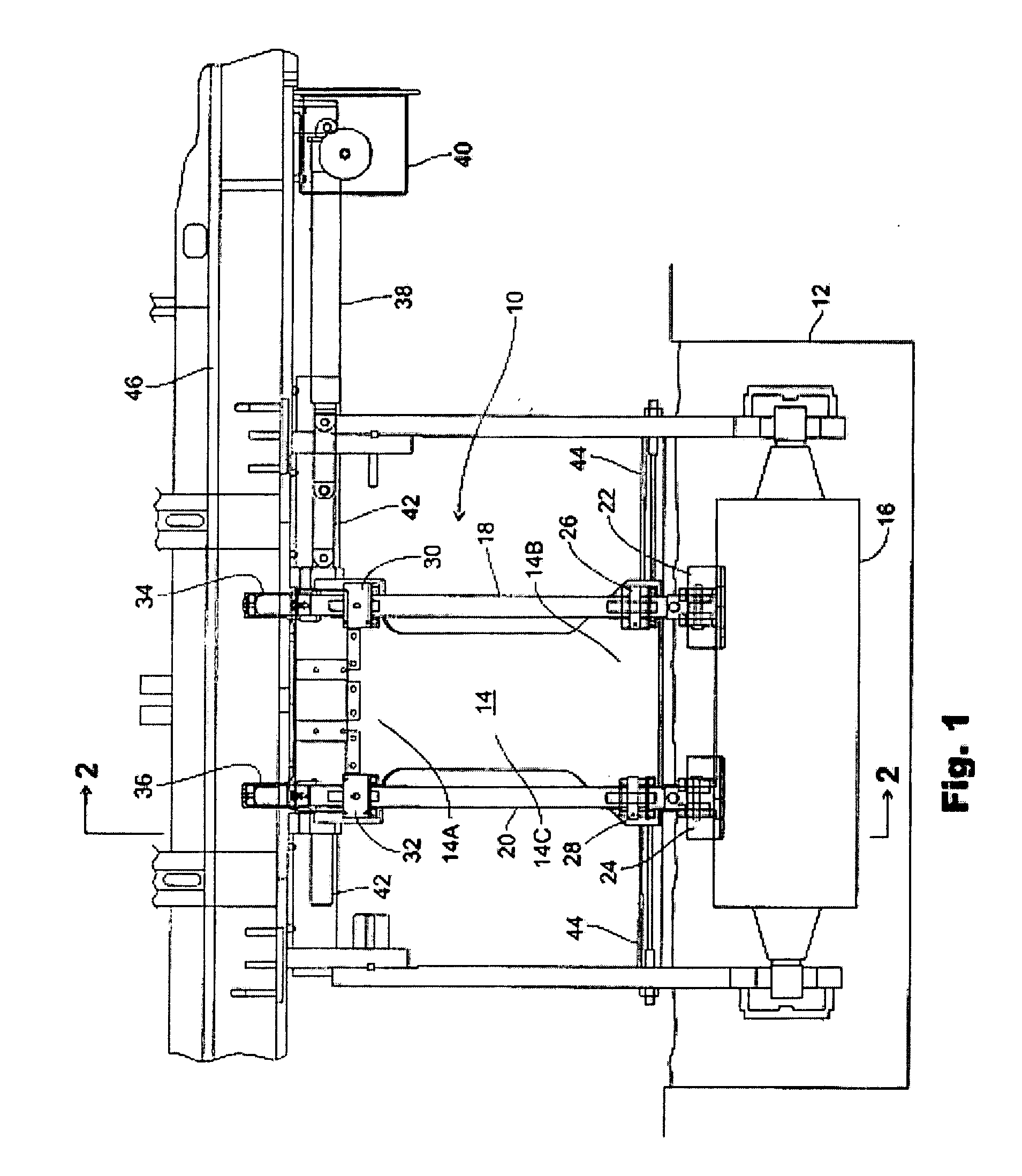
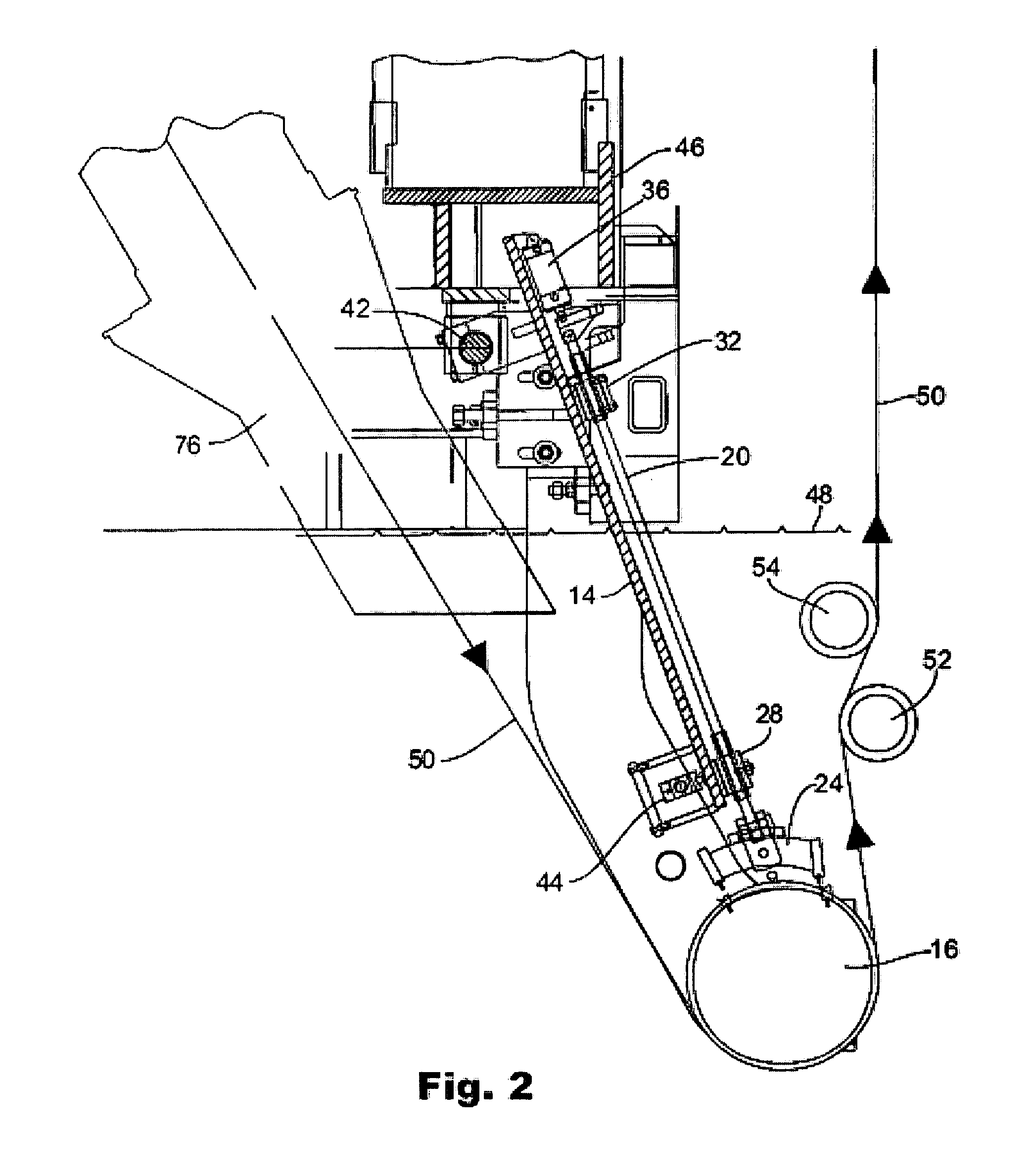
[0038] Referring to FIGS. 1 and 2, a portion of a continuous metal strip coating line is shown. The continuous steel strip 50 is fed at an oblique angle into a pot 12 containing molten zinc or zinc / aluminum alloy, passing under a sink roll 16 redirecting the strip upward and out of the pot into a pair of rollers. The sink roll is suspended in the pot from a bridge support structure 46 spanning the coating line.

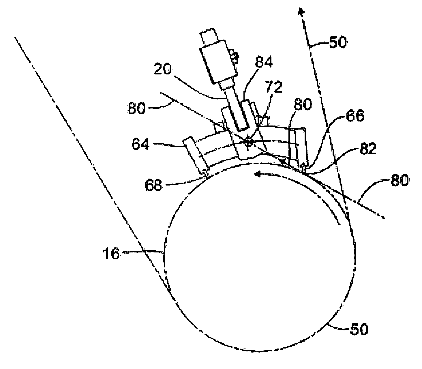
[0039] A sink roll scraper assembly is generally designated as 10. A sink roll 16 is submerged in a molten metal pot 12. The sink roll scraper assembly 10 includes a support member 14 having a pair of scraper arms 18, 20. An arm 18 or 20 is disposed at either side of support member 14. Each scraper arm 18, 20 has a scraper head assembly 22, 24 attached at an end adjacent to the sink roll 16. Scraper arm 20 at one side of the support member 14 is captured in a lower guide sleeve 26, 28 and an upper guide sleeve 30, 32, to align the scraper arm when advancing and retracting the...


PUM

PropertyMeasurementUnit
articulation angleaaaaaaaaaa
operating pressureaaaaaaaaaa
lifting pressureaaaaaaaaaa

Abstract

An apparatus for scraping the surface of a sink roll in a molten metal coating process comprises a support member having a pair of linearly movable arms supported thereon. The support member depends from a bridge structure spanning a continuous metal coating line, and a pair or arms, the arms being disposed on opposite sides of said support member. Each arm has a scraper assembly portion attached thereto. Each scraper assembly portion has two blades affixed thereto, a forward scraper blade and a rear scraper blade, with a connecting portion connecting the two blades. The connecting portion also has a first pivot point for attaching the connecting portion to the arm associated with the scraper assembly portion, the first pivot point being disposed between said forward and rear scraper blades for following the radial contours of the roll surface. A second pivot point permits the blades to follow the crown of the roll. Pneumatic cylinders advance the arms such that at least one scraper blade presses against the roll surface under pressure. There is also control means for controlling the pressure of the scraping force of said blades applied to the roll surface. A traversing means provides for communicating lateral movement of said blades laterally along the axis of the roll while scraping against the roll.

Description

CROSS-REFERENCES TO RELATED APPLICATIONS [0001] This application is a divisional of U.S. patent application Ser. No. 11 / 058,127, filed Feb. 15, 2005.FIELD OF THE INVENTION [0002] The present invention relates to an apparatus for scraping a roll surface to remove surface deposits that cause surface defects in a molten metal coating process. BACKGROUND OF THE INVENTION [0003] Continuous hot-dip galvanizing lines are known in the art. A cleaned strip of steel is heat-treated and passed from the furnace into a coating bath without being exposed to air. The coating bath contains molten zinc or zinc-aluminum (Zn—Al) alloy. As the strip emerges from the coating bath, an air knife is directed at both sides of the strip to control the weight and thickness of the coating. [0004] After the strip enters the coating bath from the submerged furnace snout, the strip is held under the surface of the liquid metal by a submerged roll called a sink roll. Inter-metallic particles and oxides form in the...

Claims


Application Information

Patent Timeline
Patent Type & Authority Applications(United States)
IPC IPC(8): B05D3/12B05C11/04
CPCC23C2/003C23C2/51C23C2/00344C23C2/50
Inventor SAPP, ERIN G.HICKMAN, MICHAEL D.BROOKS, SCOTT E.PIPER, JAMES M.
Owner NITED STATES STEEL CORP
Features
  • Generate Ideas
  • Intellectual Property
  • Life Sciences
  • Materials
  • Tech Scout
  • Unparalleled Data Quality
  • Higher Quality Content
  • 60% Fewer Hallucinations
Learn More