
Hinge buffer device

a buffer device and buffer technology, applied in multi-purpose tools, door/window fittings, construction, etc., can solve the problems of hardware fatigue and adjustment, and achieve the effects of low production cost, easy operation, and simple structur

Active Publication Date: 2008-05-15
KING SLIDE WORKS CO LTD
View PDF17 Cites 62 Cited by
  • Summary
  • Abstract
  • Description
  • Claims
  • Application Information

AI Technical Summary

Benefits of technology

[0011]It is another objective of the present invention to provide a hinge buffer device, which is simple in structure and has a low production cost.
[0012]It is a further objective of the present invention to provide a hinge buffer device, which is easy to operate, simply adjusting the knob of the bolt without the necessary of any tool.

Problems solved by technology

However, after a period of time, the hardware will fatigue and require making an adjustment.
Some of the buffer members require to adjust at least two bolts to do the alignment, which is inconvenient.

Method used


Image

  • Hinge buffer device
  • Hinge buffer device
  • Hinge buffer device

Examples


Embodiment Construction

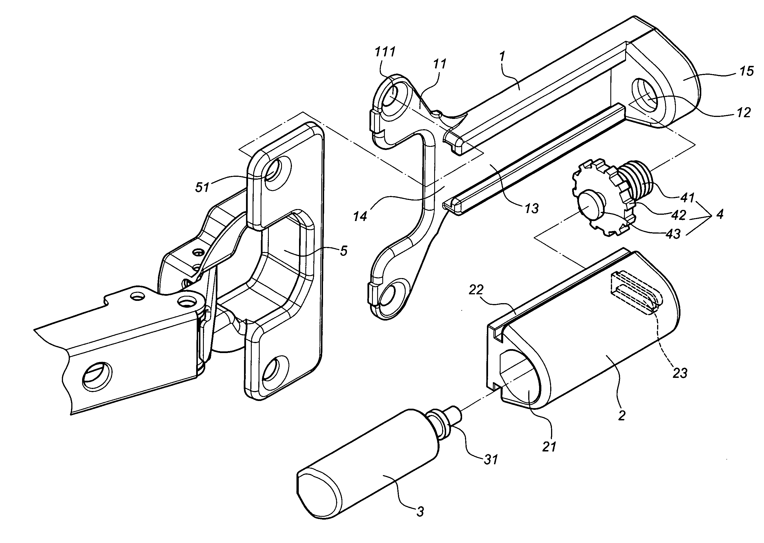
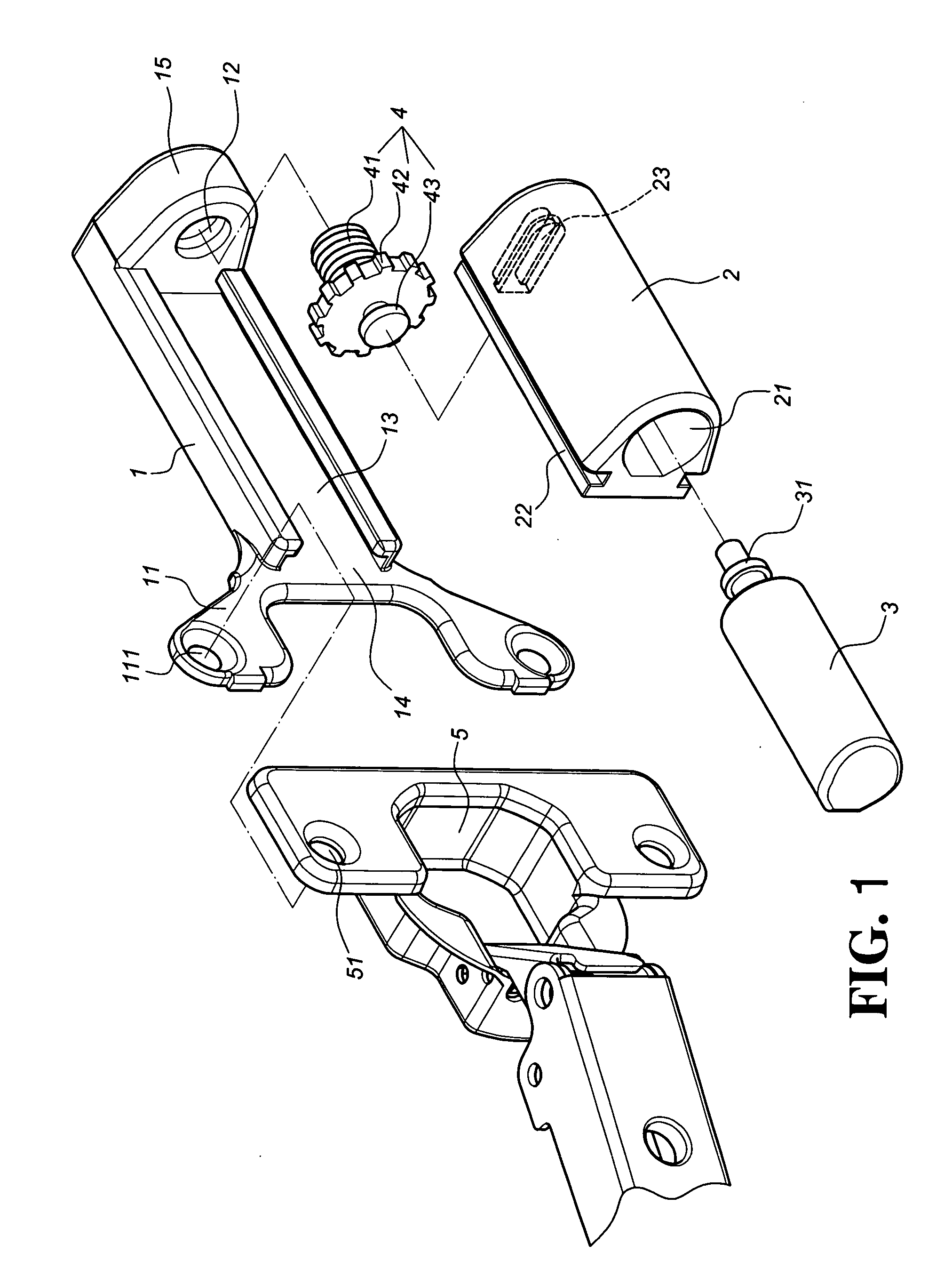
[0023]As shown in FIG. 1, a first preferred embodiment of the present invention comprises a casing 1, a slide 2, a buffer 3 and an adjustment 4.

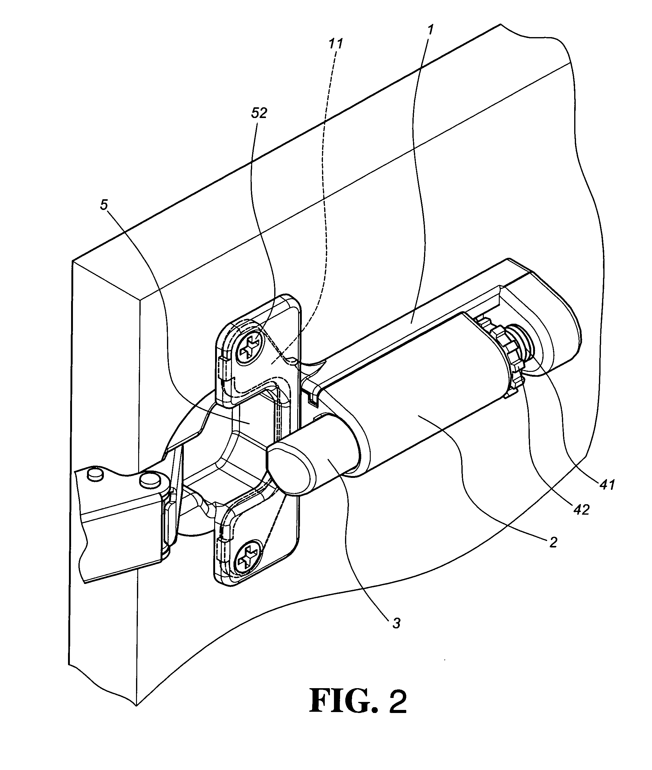
[0024]The casing 1 comprises a pair of lugs 11, a threaded hole 12 and a sliding trough 13. The lugs 11 are formed at respective sides of a first end 14 of the casing 1. Each of the lugs 11 has a through hole 111 corresponding to a threaded hole 51 of a hinge base 5, as shown in FIG. 2, for mounting purpose by means of fasteners 52 to secure the casing 1 and the casing base 5 onto a cabinet panel. The threaded hole 12 is formed at a second end 15 of the casing 1. The axis of the threaded hole 12 is parallel with the sliding trough 13. The sliding trough 13 is located between the first end 14 and the second end 15.

[0025]The slide 2 has a compartment 21 therein and a pair of sliding sections 22 at respective sides thereof corresponding to the sliding trough 13 of the casing 1. A T-shaped trough 23 is formed at one end of the slide 2.

[0026]The ...


PUM


Abstract

A hinge buffer device includes a casing, a slide, a buffer and an adjustment. The casing comprises a first end, a second end, a pair of lugs, a threaded hole, and a sliding trough. The lugs are disposed at two sides of the first end of the casing. The threaded hole is formed at the second end of the casing. The sliding trough is located between the first end and the second end of the casing. The slide comprises a compartment, a pair of sliding sections at respective sides to be engaged with the sliding trough of the casing. The buffer is a cylinder to be mounted in the compartment of the slide. The buffer comprises a piston rod secured to the slide. The adjustment is connected to the slide, and comprises a bolt to be engaged with the threaded hole of the casing.

Description

BACKGROUND OF THE INVENTION[0001]1. Field of the Invention[0002]The present invention relates to a hinge buffer device, in particular to a device having an adjustment to adjust the position and the buffer force of a buffer.[0003]2. Description of the Prior Art[0004]A conventional furniture hinge comprises a hinge base, a hinge arm and a fixed plate. The hinge arm is pivotally connected to the hinge base in an expandable status. The hinge base is usually secured to a panel while the hinge arm is secured to the fixed plate on a cabinet. The hinge arm is provided with an elastic member to restore the panel back to its original position so as to cover the cabinet. However, the panel mounted with the hinge of the prior art will hit the cabinet directly without any buffer force. Therefore, some of the cabinets are installed with a buffer device to avoid a direct hit of the panel to the cabinet.[0005]Most of the buffer devices comprise a casing and a buffer member. The buffer member is dis...

Claims


Application Information

Patent Timeline
IPC IPC(8): E05F3/20E05D11/06E05F5/10
CPCE05D11/06Y10T16/304E05F5/10E05Y2201/21E05Y2201/256E05Y2201/264E05Y2201/676E05Y2201/702E05Y2600/20E05Y2600/46E05Y2900/20Y10T16/62Y10T16/283Y10T16/5383E05F5/006E05Y2600/12E05Y2600/312E05Y2800/00
Inventor CHEN, KEN-CHINGHUANG, TING-TSAIWANG, CHUN-CHIANG
Owner KING SLIDE WORKS CO LTD
Features
  • Generate Ideas
  • Intellectual Property
  • Life Sciences
  • Materials
  • Tech Scout
  • Unparalleled Data Quality
  • Higher Quality Content
  • 60% Fewer Hallucinations
Learn More