Substrate heating device

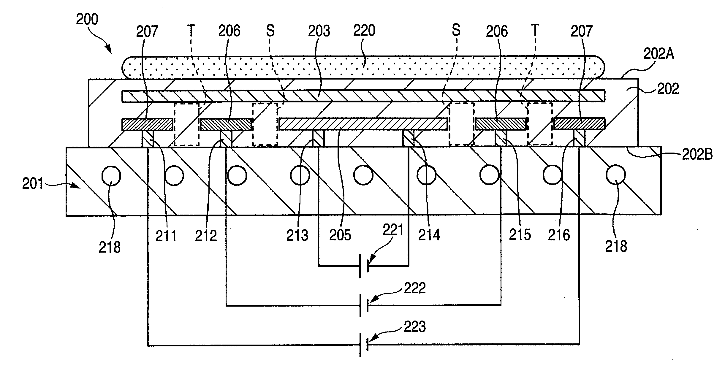
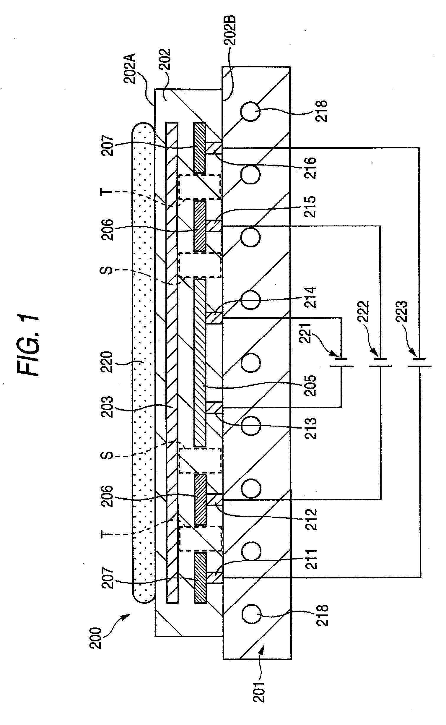
a heating device and substrate technology, applied in the direction of ohmic-resistance heating, hot plate heating arrangement, manufacturing tools, etc., can solve the problem that the substrate b>220/b> cannot be heated to a predetermined temperatur

Inactive Publication Date: 2008-05-15
SHINKO ELECTRIC IND CO LTD
View PDF6 Cites 24 Cited by
  • Summary
  • Abstract
  • Description
  • Claims
  • Application Information

AI Technical Summary

Benefits of technology

[0022] According to the present invention, the first resistance heating body that has an area that is substantially equal to the first main surface of the ceramic plate on which the substrate is loaded and is arranged in substantially parallel with the first main surface of the ceramic plate, and the second resistance heating body arranged in the predetermined position between the first main surface of the ceramic plate and the first resistance heating body and/or b...

Problems solved by technology

As a result, such a problem existed that the subst...

Method used


Image

  • Substrate heating device
  • Substrate heating device
  • Substrate heating device

Examples


first embodiment

[0041]FIG. 3 is a sectional view of a substrate heating device according to a first embodiment of the present invention.

[0042] By reference to FIG. 3, a substrate heating device 10 of the first embodiment includes a base plate 11, a ceramic plate 12, an electrostatic electrode 13, first resistance heating bodies 14 to 16, electrodes 21 to 26, 33 to 36, second resistance heating bodies 28, 29, and power supplies 41 to 45.

[0043] The base plate 11 is the platform on which the ceramic plate 12 is held. A pipeline 47 through which the cooling water circulates is formed in the base plate 11. The cooling water flowing through the pipeline 47 cools the ceramic plate 12 to control a temperature of a substrate loading surface 12A (a first main surface of the ceramic plate 12).

[0044] The ceramic plate 12 is provided on the base plate 11. The ceramic plate 12 has the substrate loading surface 12A on which a substrate 40 is loaded. As the material of the ceramic plate 12, for example, nitride...

second embodiment

[0080]FIG. 7 is a sectional view of a substrate heating device according to a second embodiment of the present invention. In FIG. 7, the same reference symbols are affixed to the same constituent portions as the substrate heating device 10 according to the first embodiment.

[0081] By reference to FIG. 7, a substrate heating device 50 of the second embodiment is constructed similarly to the substrate heating device 10 of the first embodiment, except that electrodes 51 to 56, 61 to 64 are provided instead of the electrodes 21 to 26, 33 to 36 provided to the substrate heating device 10 and that the positions in which the first resistance heating bodies 14 to 16 and the second resistance heating bodies 28, 29 are provided in the first embodiment are changed respectively.

[0082] The first resistance heating bodies 14 to 16 are built in the portion of the ceramic plate 12 positioned below the electrostatic electrode 13 but over the second resistance heating bodies 28, 29. The first resist...

third embodiment

[0103]FIG. 8 is a sectional view of a substrate heating device according to a third embodiment of the present invention. In FIG. 8, the same reference symbols are affixed to the same constituent portions as the substrate heating device 10 according to the first embodiment. In FIG. 8, K denotes an outer peripheral portion of the substrate 40 (referred to as a “substrate outer peripheral portion K” hereinafter).

[0104] By reference to FIG. 8, a substrate heating device 70 of the third embodiment is constructed similarly to the substrate heating device 10 of the first embodiment, except that a third resistance heating body 71, electrodes 72, 73, and a power supply 75 are provided in addition to the configuration of the substrate heating device 10.

[0105]FIG. 9 is a plan view of a third resistance heating body provided to the substrate heating device shown in FIG. 8.

[0106] By reference to FIG. 8 and FIG. 9, the third resistance heating body 71 is formed like a ring shape. This third re...


PUM

PropertyMeasurementUnit
Timeaaaaaaaaaa
Temperatureaaaaaaaaaa
Electrical resistanceaaaaaaaaaa

Abstract

A substrate heating device includes a ceramic plate on which a substrate is loaded, and first resistance heating bodies built in the ceramic plate, whereby the first resistance heating bodies are arranged on a same planar surface in substantially parallel with a substrate loading surface of the ceramic plate such that adjacent first resistance heating bodies are separated mutually and the first resistance heating bodies are constructed such that a temperature is controlled independently respectively, and also includes second resistance heating bodies built in the ceramic plate to heat portions of the ceramic plate positioned between the first resistance heating bodies.

Description

[0001] This application claims priority to Japanese Patent Application No. 2006-300971, filed Nov. 6, 2006, in the Japanese Patent Office. The priority application is incorporated by reference in its entirety. TECHNICAL FIELD [0002] The present disclosure relates to a substrate heating device. More particularly, the present disclosure relates to a substrate heating device having resistance heating bodies built in a ceramic plate to heat a substrate. RELATED ART [0003] In the apparatuses such as the film forming apparatus for forming a film on a glass substrate, a semiconductor substrate, or the like, the etching apparatus for patterning the film formed on the substrate, and the like, the substrate heating device for loading the substrate thereon and heating the loaded substrate to a predetermined temperature is provided (see FIG. 1). [0004]FIG. 1 is a sectional view of the substrate heating device in the related art. [0005] By reference to FIG. 1, a substrate heating device 200 incl...

Claims


Application Information

Patent Timeline
IPC IPC(8): H05B3/68
CPCH05B3/143H01L21/67103H05B3/283H01L21/324H01L21/477
Inventor HAYASHI, NAOTOYONEKURA, HIROSHITAMAGAWA, KOKI
Owner SHINKO ELECTRIC IND CO LTD
Why Eureka
Try Eureka