Imaging apparatus with function of shading compensation

a technology of limb darkening and compensation, which is applied in the direction of exposure control, printing, instruments, etc., can solve the problems of inability to solve problems, long time to compensate for limb darkening of an optical system, and first conventional techniqu

Inactive Publication Date: 2008-05-15
CASIO COMPUTER CO LTD
View PDF6 Cites 14 Cited by
  • Summary
  • Abstract
  • Description
  • Claims
  • Application Information

AI Technical Summary

Benefits of technology

[0007] Assuming that a dark current component having a level of P′ is contained in one image photographed with the exposure time T1, “P′>P” will be true. Therefore, the dark current component “P” contained in the combined image 5 can be decreased, whereby the image photographed with a long exposure time is improved in image quality.
[0008] The first conventional technique mentioned above has advantages in improving image quality of an image photographed with a long exposure time. But on the contrary the first conventional technique has disadvantages that cannot solve problems caused due to camera shake, which occurs frequently.
[0015] As described above, the second conventional technique solves problems caused due to camera shake by correcting the movement or displacement between images adjacent in terms of time. And further, dark current components contained in the combined image 10 is reduces, whereby an image photographed with a long exposure time is improved in quality.
[0021] Japanese Patent Application 2002-296685 A describes a technique (hereinafter, a “third conventional technique”) that increases brightness at a point on the image 18 shown in FIG. 14 as the point moves to edge of the image, thereby solving the problem of limb darkening without increasing costs.

Problems solved by technology

But on the contrary the first conventional technique has disadvantages that cannot solve problems caused due to camera shake, which occurs frequently.
However, the second conventional technique has another disadvantages that it takes a long time to compensate for limb darkening of an optical system, as described below.
In actual situation, the above devices need substantial production costs, and therefore it is common that these devices are employed only in some single-lens reflex cameras.
However, when the third conventional technique (a method of processing an image to compensate for limb darkening in the image) is applied to the second conventional technique without any modification made to said third conventional technique, it is hard to make brightness distribution flat or even over the finally obtained image 10 which is subjected to limb darkening effect.
FIG. 15 is a view illustrating disadvantages caused by the conventional techniques.
As a result, a problem is yielded that the more images have to be compensated, the longer time is required to compensate for limb darkening in the images.

Method used


Image

  • Imaging apparatus with function of shading compensation
  • Imaging apparatus with function of shading compensation
  • Imaging apparatus with function of shading compensation

Examples


first embodiment

of the Invention

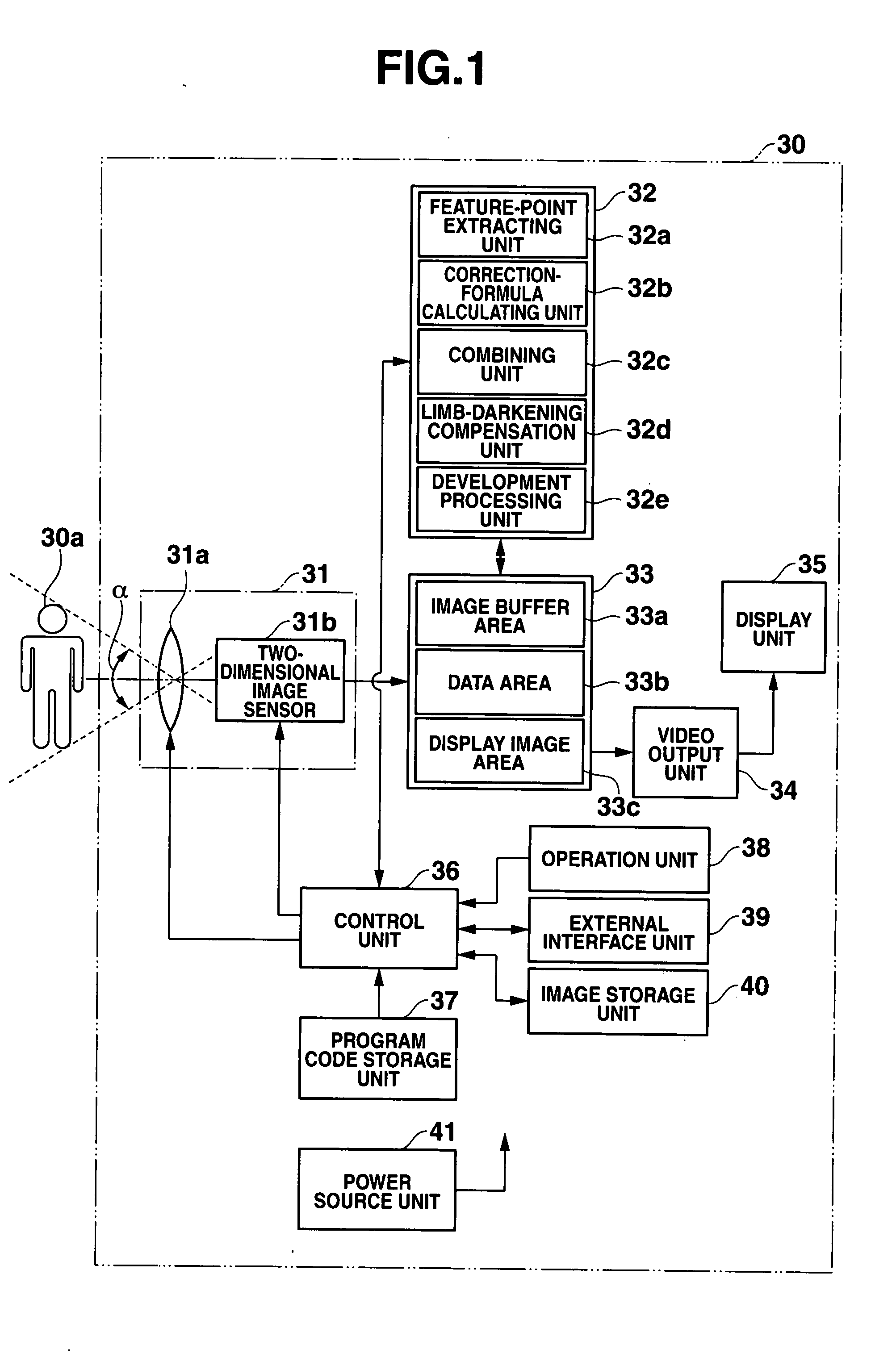
[0061]FIG. 1 is a block diagram showing a configuration of a digital camera.

[0062] The digital camera 30 comprises an image pick-up unit 31, image processing unit 32, memory unit 33, video output unit 34, display unit 35, control unit 36, program code storage unit 37, operation unit 38, external interface unit 39, image storage unit 40 and power source unit 41.

[0063] The image pick-up unit 31 has an optical system 31a and a two-dimensional image sensor 31b. The optical system 31a includes a photographic lens which comprises a single lens or an assembly of plural lenses, aperture adjustment mechanism, focus adjustment mechanism, and a zoom mechanism for adjusting an angle “α” of view (or focal length). The two-dimensional image sensor 31b consists of a semi-conductor device such as CCD sensor and CMOS sensor.

[0064] Operation of the image pick-up unit 21 is controlled in accordance with instructions of photographing operation sent from the control unit 36. The opera...

second embodiment

of the Invention

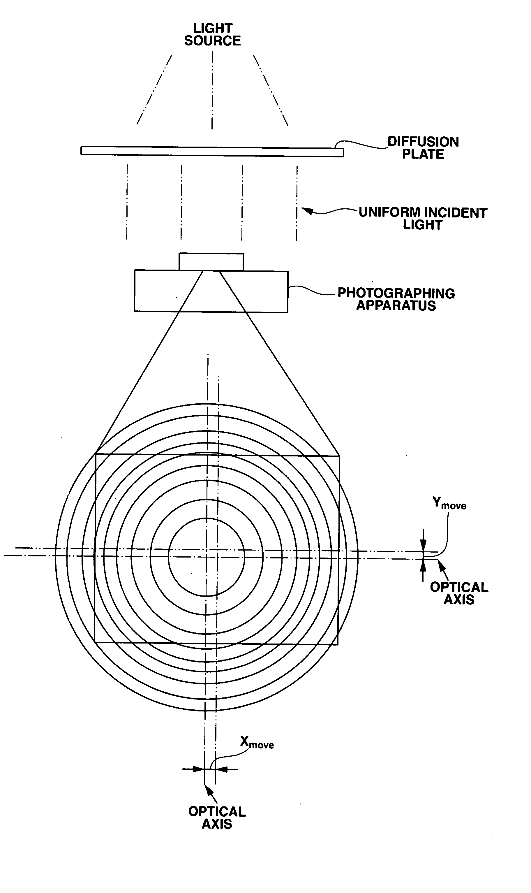
[0163] In general, brightness at an optical axis of the optical lens is used as reference brightness, and limb-darkening compensation is made with reference to such reference brightness. In average cameras, there is slight displacement between the optical axis of the lens and the center of a light receiving plane (image pick-up plane of the two-dimensional image sensor 31b). Therefore, common data cannot be compensated for correctly.

[0164] In the case if the displacement between the optical axis of the lens and the center of a light receiving plane is detected in each camera, each camera is used to take a picture with a complete light-diffusion plate provided thereon in uniform incident-light conditions, and the center of the picture is calculated from the picture data. This troublesome process can be bars in production line.

[0165] The second embodiment of the invention provides a method of calculating a limb-darkening compensation value common to individual camera...

third embodiment

of the Invention

[0176]FIGS. 10A, 10B and 10C are views illustrating an idea of a digital zoom technique.

[0177] In the case of the digital zoom technique which enlarges a photographed image at an arbitrary enlarging ratio, the limb darkening effect is caused in photograph data 65 due to characteristics of an optical lens, and an available area is only a center portion 67 of an imaging area 66 of the two-dimensional image sensor.

[0178] If the limb darkening compensation is made in the enlarged photograph image 65, calculation is possible based on compensation values due to the optical lens, whereby compensation is made over an image in an area expanding wider than the available area (center portion 67 of the imaging area 66 of the two-dimensional image sensor). Therefore, such compensation is not effective.

It will be more effective to make compensation for limb darkening in an image limited to the available area (center portion 67 of the imaging area 66 of the two-dimensional imag...


PUM


Abstract

A photographing unit photographs an object “n” times respectively with exposure times T1(1) to T1(n) to generate “n” sheets of images of the same object per an exposure time T1, where “n” is a whole number and the exposure times T1(1) to T1(n) are obtained by dividing the exposure time T1 by the whole number of “n”, a displacement correcting unit (32a, 32b) calculates a correction value for correcting displacement of the images, and a limb-darkening compensating unit (32d) corrects a position of a limb-darkening characteristic component of each of the images, using the correction value. Meanwhile, the limb-darkening characteristic components of the images whose positions have been corrected are combined to generate a limb-darkening characteristic component for compensation. Limb darkening in a combined image is compensated for, using the limb-darkening characteristic component for compensation, whereby a time required for performing a limb-darkening compensating process is decreased.

Description

which combine photographs to improve deterioration of image quality of a photograph that can be caused during shooting operation with a long exposure time. [0001]FIG. 12 is a view showing a general idea of the first conventional technique. In FIG. 12, T1 denotes an exposure time for shooting an object under low light conditions where it is prohibited to use a strobe light. The exposure time T1 is an exposure time that is longer than an appropriate time for shooting under good light conditions. In the first conventional technique, an image signal is read out from the two-dimensional image sensor several times during the exposure time T1. [0002] For instance, the exposure time T1 is evenly divided into four exposure times, T1(1) to T1(4), as shown in FIG. 12, and images are read out from the image sensor respectively in four exposure times T1(1) to T1(4). Note that the exposure time T1 is not always divided evenly but may be simply divided into plural exposure times. [0003] Finall...

Claims


Application Information

Patent Timeline
Patent Type & Authority Applications(United States)
IPC IPC(8): H04N5/335G03B5/00G03B7/08H04N5/232H04N5/243H04N101/00
CPCH04N5/3572H04N5/23232H04N23/951H04N23/60H04N25/61
Inventor MAKINO, TETSUJISAKURAI, KEIICHI
Owner CASIO COMPUTER CO LTD
Why Eureka
Try Eureka