Zoom lens system

a zoom lens and lens body technology, applied in the field of zoom lens systems, can solve the problems of aberration fluctuations, long overall length significant increase of cost, volume and weight of the zoom lens system, etc., and achieve the effect of reducing the number of constituent lenses and high image resolution

Active Publication Date: 2008-05-15
ASIA OPTICAL INT LTD
View PDF4 Cites 8 Cited by
  • Summary
  • Abstract
  • Description
  • Claims
  • Application Information

AI Technical Summary

Benefits of technology

[0006]To overcome the above disadvantages in the prior art, the object of the present invention is to provide a four-group zoom lens system that consists of a reduced number of constituent lenses while offering a four-times zoom ratio and a high image resolution. The present zoom lens system adopts two plastic aspheric lenses and a resin hybrid lens to reduce the number of constituent lenses.
[0007]It is known that, to increase the zoom ratio of a zoom lens system, two methods may be employed. One method is to increase the refractive power of the zooming lens group, which will bring the problem of aberration fluctuations during zooming. The other method is to increase the movement amount of the zooming lens group. However, when three lens groups are adopted to provide an increased zoom ratio such as a four-times zoom ratio, an increased movement space is required, which results in a long overall length of the zoom lens system. When four lens groups are adopted, the movement space can be reduced. However, for a four-group zoom lens system, when the constituent lenses are all spherical lenses, a large amount of spherical lenses must be used for effective aberration correction. This results in a significant increase of the cost, the volume and the weight of the zoom lens system. To overcome these problems, aspheric lenses may be employed for effective aberration correction. To further reduce the manufacture cost, the aspheric lenses may be injection molded with plastic material.
[0011]The second and third lens groups of the present zoom lens system satisfy the following condition:0.55<F2F3<1.2where F2, as indicated above, represents the focal length of the second lens group, and F3 represents the focal length of the third lens group. When the absolute value of the ratio of F2 to F3 exceeds the upper limit of 1.2, the refracting power of the third lens group increases and thus astigmatism rapidly increases. When the absolute value of the ratio of F2 to F3 is smaller than the lower limit of 0.55, the refracting power of the third lens group decreases, and thus the overall length of the entire lens system is elongated, which is apart from the compactness requirement.

Problems solved by technology

One method is to increase the refractive power of the zooming lens group, which will bring the problem of aberration fluctuations during zooming.
However, when three lens groups are adopted to provide an increased zoom ratio such as a four-times zoom ratio, an increased movement space is required, which results in a long overall length of the zoom lens system.
However, for a four-group zoom lens system, when the constituent lenses are all spherical lenses, a large amount of spherical lenses must be used for effective aberration correction.
This results in a significant increase of the cost, the volume and the weight of the zoom lens system.

Method used


Image

  • Zoom lens system
  • Zoom lens system
  • Zoom lens system

Examples


embodiment 1

[0048]Table 3 shows variable distances (in unit of millimeters) between adjacent lens groups at the respective system effective focal lengths, namely, at the wide-angle end (W, f=8.05), an intermediate zoom position (M, f=16.07) and the telephoto end (T, f=31.31) of the zoom lens system of Numerical

TABLE 3EffectiveVariableVariableVariableVariableFocal LengthDistance 1Distance 2Distance 3Distance 4W (f = 8.05)0.217.083134.3881754.437559M (f = 16.07)10.2178777.0078021.2862468T (f = 31.31)19.3342060.7999150.815

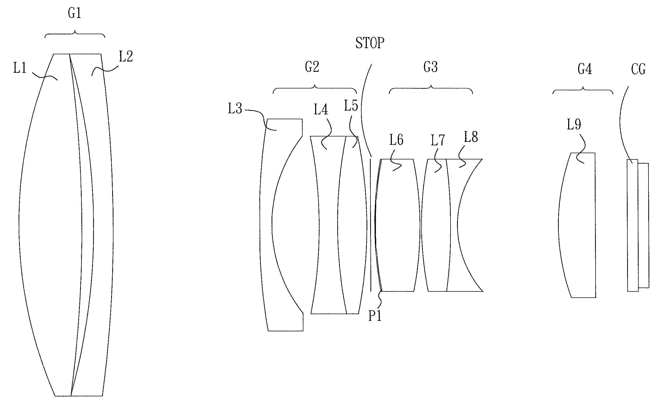
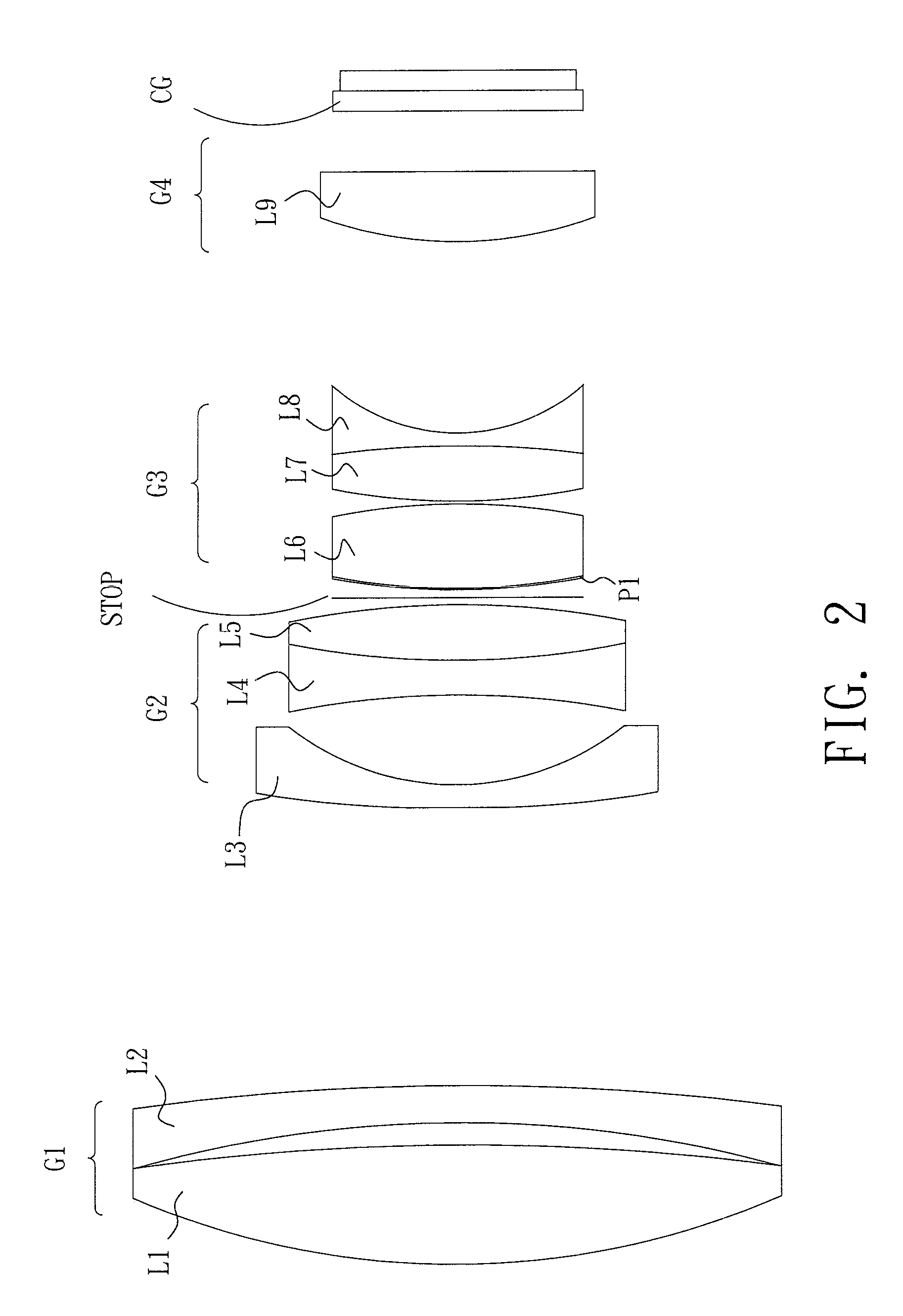
[0049]FIGS. 4 and 5 respectively show positions of lens groups constituting the zoom lens system of Numerical Embodiment 1 at the wide-angle end and the telephoto end. It is shown that, during focal length change, the first lens group G1 and the fourth lens group G4 remain stationary. The positions of the second lens group G2, the stop and the third lens group G3 are changed to obtain a desired zoom ratio and a better image. The first, second and third lens groups G1, G2 and G3 s...

embodiment 2

[0057]Table 5 shows aspheric coefficients of aspheric surfaces for Numerical It can be seen that the object-side surface of the first aspheric lens L3, the object-side surface of the resin hybrid lens L6 and the object-side surface of the second aspheric lens L9 are aspheric.

TABLE 5surface (i)KE4E6E8E10503.6868 × 10−5−1.3882 × 10⁻⁷     4.2351 × 10−100110 −1.57 × 10−49.7583 × 10−7−4.1163 × 10−86.3989 × 10−10170−6.3985 × 10⁻⁵  6.2073 × 10⁻⁷−1.1467 × 10−84.3291 × 10−11

[0058]Table 6 shows variable distances between adjacent lens groups at the respective system effective focal lengths, namely at the wide-angle end (W, f=8.09), an intermediate zoom position (M, f=16.05) and the telephoto end (T, f=31.28) of the zoom lens system of Numerical Embodiment 2.

TABLE 6EffectiveVariableVariableVariableVariableFocal LengthDistance 1Distance 2Distance 3Distance 4W (f = 8.09)0.96516.03264.62123.3118M (f = 16.05)10.5076.691.146.7124T (f = 31.28)19.6520.81.014.408

[0059]FIGS. 14 and 15 respectively sho...

embodiment 3

[0061]Table 8 shows aspheric coefficients of aspheric surfaces for Numerical It can be seen that the two surfaces of the first aspheric lens L3, the object-side surface of the resin hybrid lens L6 and the object-side surface of the second aspheric lens L9 are aspheric.

TABLE 8surface (i)KE4E6E8E10506.0725 × 10−5−2.8236 × 10⁻⁷     4.7037 × 10−109.4522 × 10−13602.2893 × 10−5 8.292 × 10⁻⁷−8.5921 × 10−90110 −1.49 × 10−45.9831 × 10−7−4.0203 × 10−87.8332 × 10−10170−7.7792 × 10⁻⁵  6.6779 × 10⁻⁷−1.4069 × 10−86.3954 × 10−11

[0062]Table 9 shows variable distances between adjacent lens groups at the respective system effective focal lengths, namely at the wide-angle end (W, f=8.1), an intermediate zoom position (M, f=16.07), and the telephoto end (T, f=31.34) of the zoom lens system of Numerical Embodiment 3.

TABLE 9EffectiveVariableVariableVariableVariableFocal LengthDistance 1Distance 2Distance 3Distance 4W (f = 8.1)0.316.69613.9153.6258M (f = 16.07)10.4776.8861.147.296T (f = 31.34)19.7790.81....


PUM


Abstract

A zoom lens system includes, in order from an object side to an image side, a first positive lens group (G1), a second negative lens group (G2), a third positive lens group (G3), and a fourth positive lens group (G4). The second and third lens groups are movable for varying the focal length. The zoom lens system offers a four-times zoom ratio, and employs two plastic aspheric lenses (L3, L9) and a resin hybrid lens (L6). The first lens group consists of two lenses (L1, L2) arranged in an abutting relationship. The second and third lens groups each includes a pair of cemented lenses (L4, L5; L7, L8).

Description

BACKGROUND OF THE INVENTION[0001]1. Field of the Invention[0002]The present invention relates to a zoom lens system, and particularly relates to a zoom lens system that includes plastic aspheric lenses and a resin hybrid lens to reduce the overall length and the cost. The zoom lens system further includes two pairs of cemented lenses and a pair of abutting lenses to facilitate assembly.[0003]2. Description of Prior Art[0004]Conventionally, an optical lens system is composed of a plurality of spherical lenses. However, spherical lenses cannot focus light from the center and periphery to the same point, which is called “spherical aberration”. The solution is to employ a number of additional spherical correction lenses or to introduce an aspheric surface. However, the employment of additional spherical correction lenses results in increase of the cost and elongation of the length of the lens system. The introduction of an aspheric surface effectively corrects aberration, and a correspo...

Claims


Application Information

Patent Timeline
Patent Type & Authority Applications(United States)
IPC IPC(8): G02B15/14
CPCG02B15/173G02B15/144113
Inventor LIAO, CHEN-CHENG
Owner ASIA OPTICAL INT LTD
Why Eureka
Try Eureka