Sampling frequency control method and protective relay

Inactive Publication Date: 2008-05-15
MITSUBISHI ELECTRIC CORP
View PDF2 Cites 6 Cited by
  • Summary
  • Abstract
  • Description
  • Claims
  • Application Information

AI Technical Summary

Benefits of technology

[0006] The present invention has been made in view of the above circumstances in the art, and an object of the invention is therefore to make it possible to control the sampling frequency accurately so that it follows a frequency variation of an AC quantity of electricity of a power system without the need for determining zero-cross points.
[0007] One aspect of the invention provides a sampling frequency control method including the steps of calculating, with a CPU, a ratio K, to an effective value of an AC quantity of electricity of a power system, of an effective value of a difference between sampled values obtained through sampling of the AC quantity of electricity at time points that are separated by a prescribed time period which relates to a sampling period which is shorter than a period of the AC quantity of electricity and corresponds to a prescribed electrical angle; and controlling a sampling frequency by controlling the sampling period on the basis of the calculated ratio K so that it follows a frequency of the AC quantity of electricity. This method makes it possible to control the sampling frequency accurately so that it follows a frequency variation of the AC quantity of electricity of the power system without the need for determining zero-cross points.
[0008] Another aspect of the invention provides a protective relay which protects a power system from a system abnormality on the basis of sampled values obtained by sampling an AC quantity of electricity of the power system at a prescribed sampling frequency, wherein the sampling frequency is controlled by controlling a sampling period by the above sampling frequency control method. Therefore, a protective relay can be provided in which the sampling frequency can be controlled accurately to as to follow a frequency variation of an AC quantity of electricity of a power system without the need for determining zero-cross points.

Problems solved by technology

There is a problem that the control may be based on calculation results including errors because zero-cross points are determined through approximation.

Method used


Image

  • Sampling frequency control method and protective relay
  • Sampling frequency control method and protective relay
  • Sampling frequency control method and protective relay

Examples


first embodiment

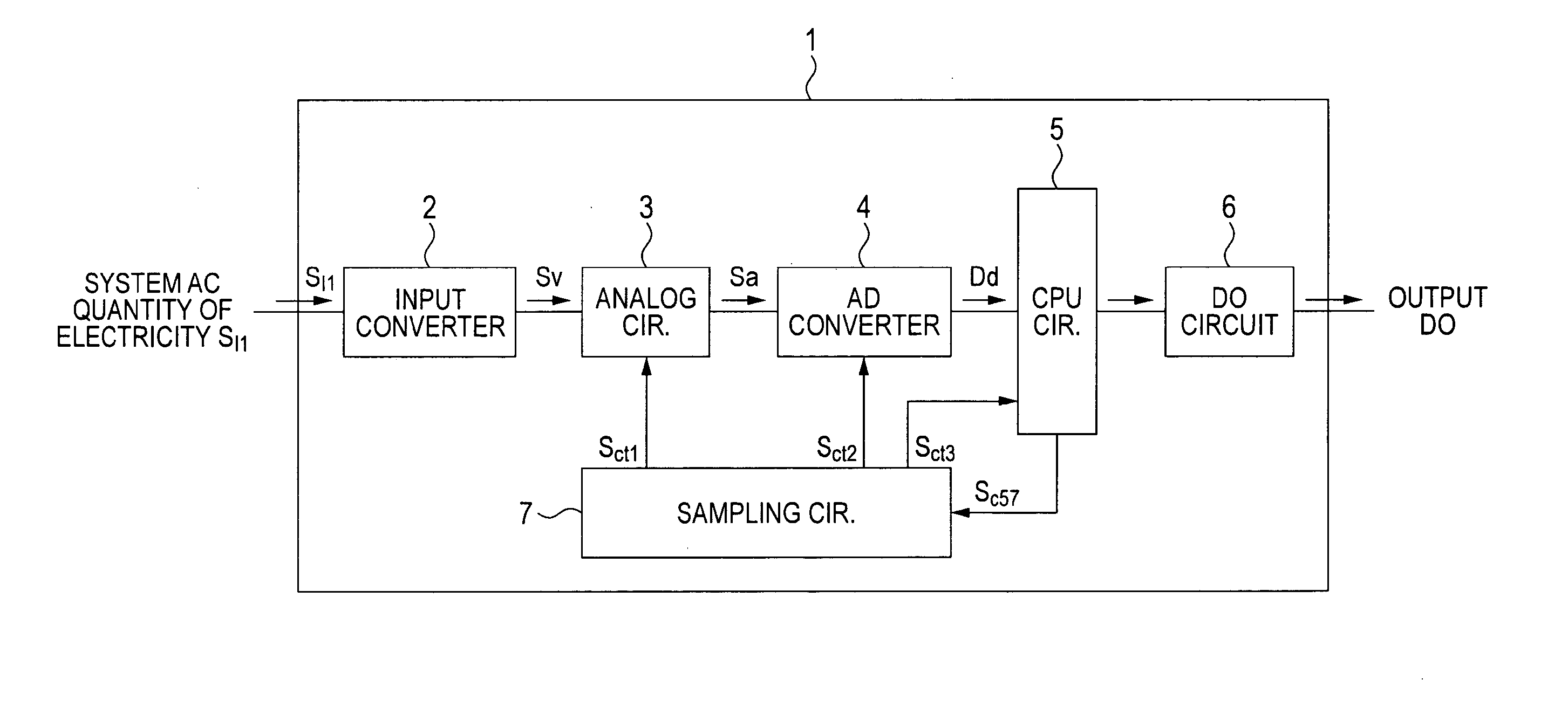
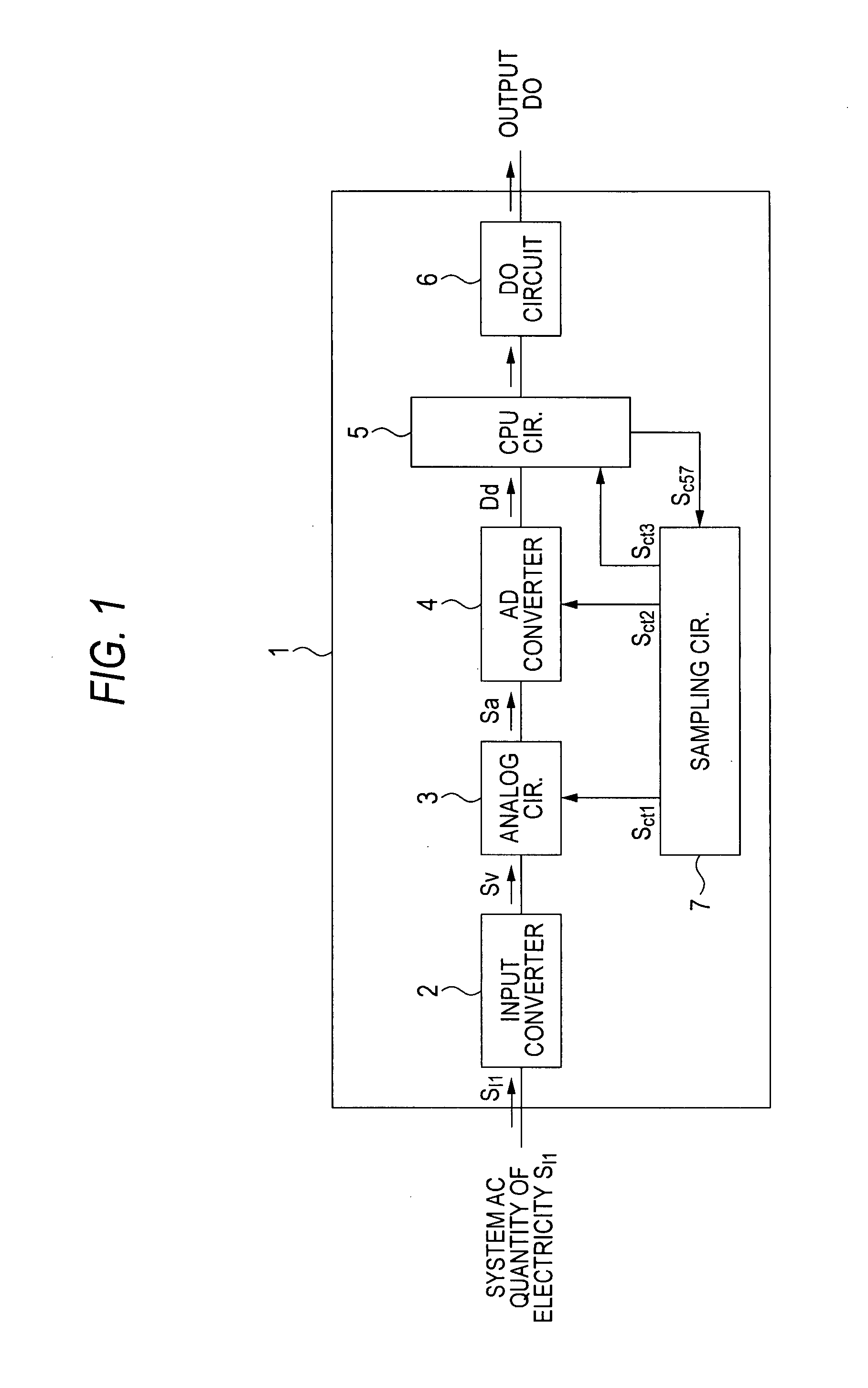
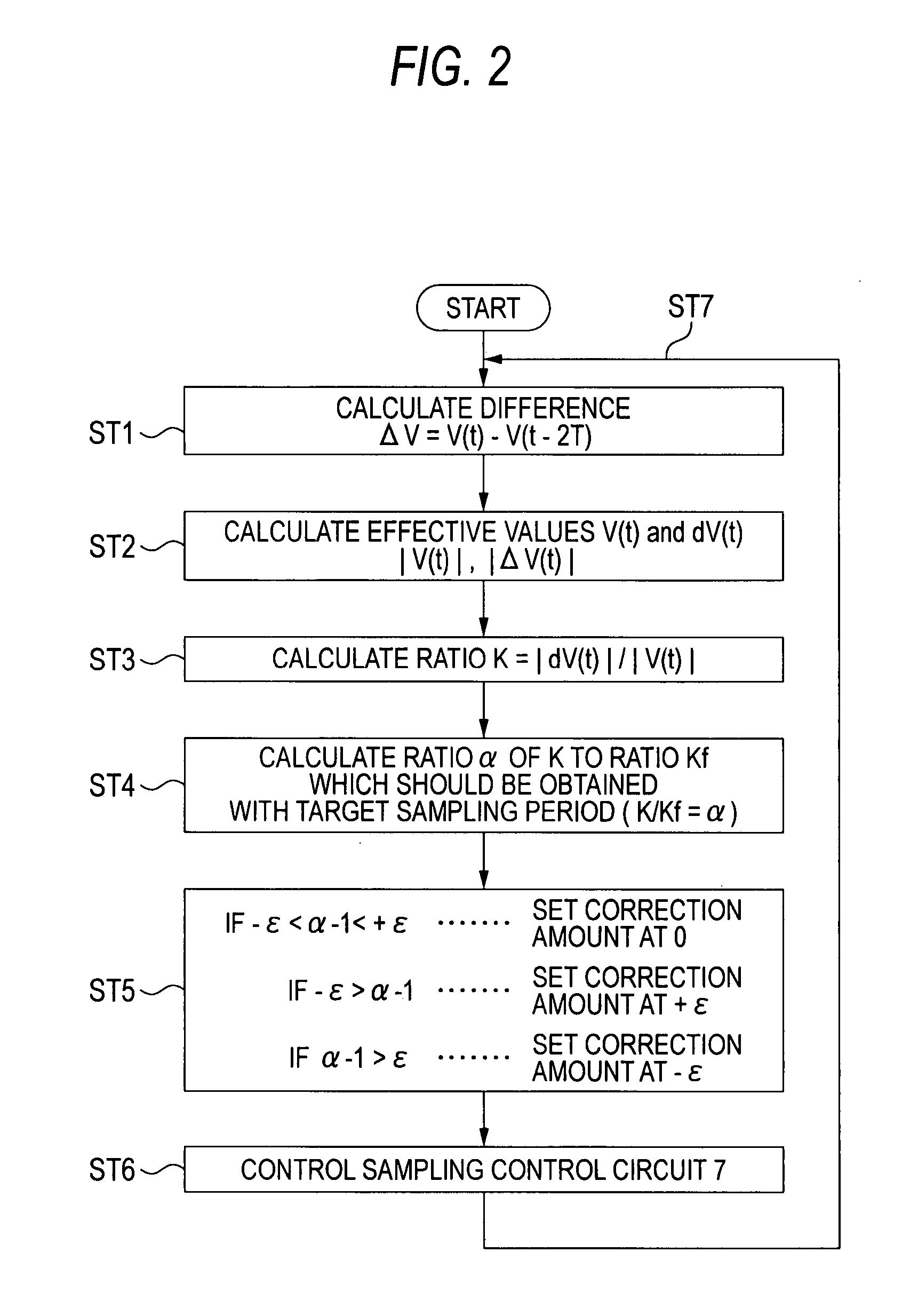
[0016] A first embodiment of the present invention will be hereinafter described with reference to FIGS. 1 and 2. FIG. 1 is a block diagram of an exemplary protective relay having a frequency following means according to the first embodiment. FIG. 2 is a flowchart of an exemplary operation of the frequency following means of the protective relay.

[0017] As shown in FIG. 1, an AC quantity of electricity SI1 such as a voltage V or a current I which is obtained from a power system via a PT or a CT is input to a protective relay 1. The input quantity of electricity SI1 is converted by an input converter 2 into a voltage signal SV which is suitable for an analog circuit 3 (provided in the protective relay 1). The voltage signal SV is input to the analog circuit 3.

[0018] Although not shown in any drawing, as is well known, the analog circuit 3 is composed of a filter circuit for eliminating harmonic components from an AC quantity of electricity, a sample-and-hold circuit for performing A...

second embodiment

[0038] Another operation of the frequency following means of the protective relay 1 according to a second embodiment of the invention will be described below with reference to a flowchart of FIG. 3.

[0039] In the above-described first embodiment, the sampling period is corrected by one unit correction amount in each set of steps ST1-ST6. In contrast, in the second embodiment, as shown in FIG. 3, at step ST5, a deviation of the sampling frequency from the system frequency of the input AC quantity of electricity is calculated on the basis of the ratio α=K / Kf that was calculated at step ST4 and a correction amount is calculated instantaneously. At step ST6, a correction is made by the thus-determined correction amount. Let the correction amount be represented by the ratio to the time 2T for the rated frequency. If one unit correction amount is represented by ε, the quotient of (α−1) / ε is a multiple of the one unit correction amount. Therefore, a correction is made by the quotient of (α...

third embodiment

[0041] Each of the first and second embodiments is provided with the means for causing the sampling frequency to follow the frequency of a system AC quantity of electricity. In contrast, a third embodiment is characterized in being provided with a means for measuring a frequency of an input AC quantity of electricity from a correction amount.

[0042] The third embodiment of the invention will be described below in a specific manner with reference to FIGS. 4 and 5. FIG. 4 is a flowchart of still another exemplary operation of the frequency following means of the protective relay 1. FIGS. 5A and 5B illustrate frequency computation.

[0043] As shown in FIG. 4, immediately after the protective relay 1 is powered on and computation is started, the sampling period is set at a value corresponding to an electrical angle for a system rated frequency.

[0044] If the frequency of an input quantity of electricity is deviated from the rated frequency, the sampling period is caused to follow the fre...


PUM


Abstract

A sampling frequency control method includes a difference calculating step ST1 of calculating the difference between sampled values obtained through sampling of an AC quantity of electricity of a power system at time points that are separated by a prescribed time period of the AC quantity of electricity; an effective value calculating step ST2 of calculating an effective value of the AC quantity of electricity and an effective value of the difference; a ratio calculating step ST3 of calculating the ratio K of the effective value of the difference to the effective value of the AC quantity of electricity; and a control step of controlling the sampling frequency by controlling the sampling period on the basis of the calculated ratio K so that it follows the frequency of the AC quantity of electricity.

Description

BACKGROUND OF THE INVENTION [0001] 1. Field of the Invention [0002] The present invention relates to a sampling frequency control method which is applied to, for example, a digital protective relay for protecting a power system from a system failure on the basis of sampled values obtained by sampling an AC quantity of electricity of the power system at a prescribed sampling frequency, as well as to a protective relay in which the sampling frequency is controlled by the above sampling frequency control method. [0003] 2. Description of the Related Art [0004] In conventional digital protective relays, a sampling frequency control for varying the sampling period so that it follows the frequency of an input AC signal is performed in the following manners. JP-A-2-13220 (FIG. 1 and a related description) discloses a technique that the period of an input AC signal is calculated on the basis of intervals of zero-cross points where the polarity of the input signal changes and the sampling per...

Claims


Application Information

Patent Timeline
IPC IPC(8): H02H3/00G01R21/00
CPCG01R19/2513G01R19/2509H02H3/38
Inventor ODA, SHIGETOO
Owner MITSUBISHI ELECTRIC CORP
Why Eureka
Try Eureka