Cement bond analysis

a cement bond and analysis method technology, applied in the field of cement bond analysis, can solve the problems of difficult assessment of cement and formation rock bond quality, poor cementing job performance, and inability to cover the casing

Active Publication Date: 2008-05-15
BAKER HUGHES INC
View PDF24 Cites 49 Cited by
  • Summary
  • Abstract
  • Description
  • Claims
  • Application Information

AI Technical Summary

Problems solved by technology

The quality of the bond between cement and formation rock, however, can be difficult to assess due to the lack of means to quantify the cement layer parameters.
For example, if the cement thickness adjacent a section of casing is found to be significantly different from that on an azimuthally opposed section, then the casing may not be centered in the borehole, indicating a poorly performed cementing job.
However, the acoustic energy penetration through casing into the cement layer of some of these prior art acoustic techniques is limited by the high impedance contrast between casing and borehole fluid.
In some of these devices, the acoustic waves are directed radially or at an angle to the casing surface and thus the highly rigid casing impairs the energy transmission into the casing.
Additionally, it may be difficult to characterize the reflection signals arising from the inner and outer walls of the cement using prior art devices.
The interference of currently used wave modes seriously impairs the recognition of the reflection effect; the interference of the wave modes and their reflections occurs when the wavelength in the cement layer becomes comparable with or exceeds cement layer thickness, which is a common scenario in oil field conditions.
Moreover, these waves are also highly dispersive in the frequency range of the reflection measurement, making it difficult to characterize the reflection signals when the interference occurs.

Method used


Image

  • Cement bond analysis
  • Cement bond analysis
  • Cement bond analysis

Examples


Embodiment Construction

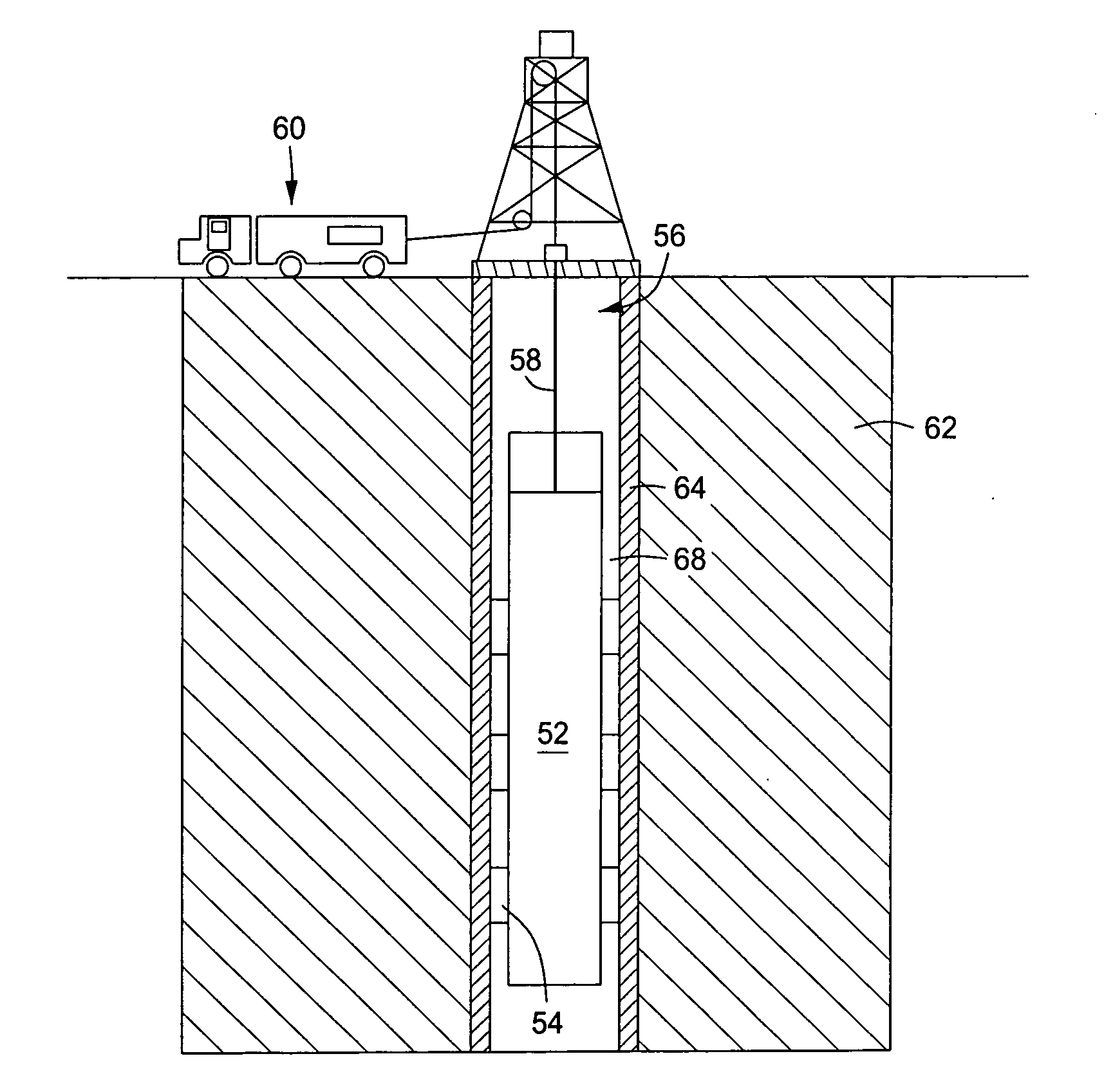
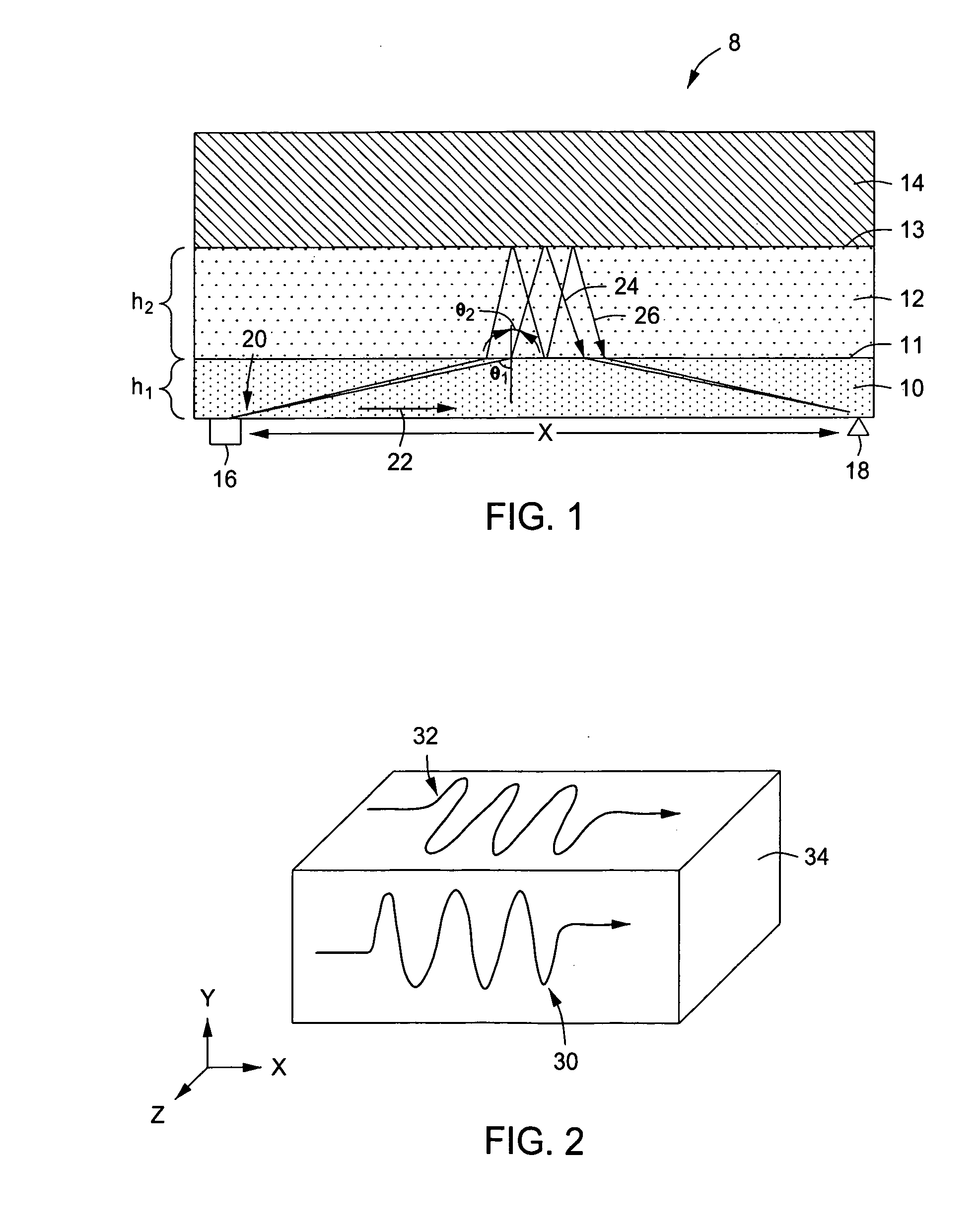
[0018]In an embodiment of the method and device herein described, acoustic waves are induced into a bonding material and the resulting signal within is measured and analyzed. With regard now to FIG. 1, an example of an acoustic signal 20 is shown propagating through a cross sectional portion of a cased downhole wellbore 8. The cased wellbore 8 of FIG. 1 includes a section of casing 10, a layer of cement 12, and a downhole formation 14, where the cement 12 adheres the casing 10 to the formation 14. A source 16 for generating the acoustic signal 20 is provided at a first location and a receiver 18 for receiving the acoustic signal 20 is disposed at a second location. As shown in FIG. 1, the distance between the source 16 and the receiver 18 is denoted by the reference identifier “x”. As elaborated below, the signal source 16 and the signal receiver 18 can be included with a downhole tool 28 used for casing bond evaluation. The source 16 for generating the acoustic signal 20 may compri...


PUM


Abstract

A method and apparatus for evaluating a bond between a formation and a bonding material. The method includes emitting a shear wave into the tubular, recording the response of the shear wave, and evaluating the response to obtain bond information. The bond information includes bond material thickness and efficacy of the bond between cement and formation. The method includes studying and utilizing the time lag of the direct wave and wave events, as well as the interference of these waves on a spectral graph. A calibration method is included as well.

Description

BACKGROUND OF THE INVENTION[0001]1. Field of the Invention[0002]The present disclosure relates to a device and a method for evaluating a cement bond. More specifically, the present disclosure relates to a device and method for evaluating the thickness, quality, and presence of a cement bond. Yet more specifically, the present disclosure concerns a device and method for evaluating a cement bond between cement and formation.[0003]2. Description of Related Art[0004]Hydrocarbon producing wellbores typically comprise casing 8 set within the wellbore 5, where the casing 8 is bonded to the wellbore by adding cement 9 within the annulus formed between the outer diameter of the casing 8 and the inner diameter of the wellbore 5. The cement bond not only adheres the casing 8 within the wellbore 5, but also serves to isolate adjacent zones (Z1 and Z2) within the formation 18 from one another. Isolating adjacent zones can be important when one of the zones contains oil or gas and the other zone ...

Claims


Application Information

Patent Timeline
Patent Type & Authority Applications(United States)
IPC IPC(8): E21B47/00G01V1/40
CPCE21B47/0005G01V1/50G01B17/02E21B47/005E21B47/00
Inventor TANG, XIAO MINGBOLSHAKOV, ALEXEIDOMANGUE, EDWARD
Owner BAKER HUGHES INC
Why Eureka
Try Eureka