
FLIR-to-missile boresight correlation and non-uniformity compensation of the missile seeker

Active Publication Date: 2008-05-15
RAYTHEON CO
View PDF9 Cites 17 Cited by
  • Summary
  • Abstract
  • Description
  • Claims
  • Application Information

AI Technical Summary

Benefits of technology

[0011]The present invention provides for simple and streamlined boresight correlation of FLIR-to-missile video and for higher bandwidth, higher SNR, user friendly NUC of IR imagers. The NUC process also provides the capability of displaying enhanced imagery.
[0012]This is accomplished in part with a method that performs boresight correlation with un-NUCed missile video. This allows boresight correlation and NUC to be performed simultaneously thereby reducing the time required to acquire a target and fire the missile. The current approach uses the motion of the missile seeker for NUCing to produce spatial gradient filtering in the missile image by differencing images as the seeker moves. This compensates DC non-uniformities in the image. Although there are residual artifacts from scene content and gain non-uniformities, they are not sufficiently severe to interfere with correlation when proper pre-filtering is used. A FLIR image is processed with a matching displace and subtract spatial filter constructed based on the tracked scene motion. The FLIR image is resampled to match the missile image resolution, and the two images are preprocessed and correlated using conventional methods.
[0013]Although this method of boresight correlation can be used in tandem with conventional techniques for NUC, additional advantages of increased bandwidth, improved SNR of the missile video and less operator involvement can be realized with improved scene-based NUC. The current approach works by cross-referencing multiple measurements of each area of the scene as viewed by different pixels in the imager. This approach is based on the simple yet novel premise that every pixel in the array that looks at the same thing should see the same thing. As a result, the NUC terms adapt to non-uniformities in the imager and not the scene.
[0015]This process can be enhanced by keeping track of the variability in the forward mapping (creating the registered average image) and / or backward mapping (estimating the ideal input images) and weighting those imager and or scene pixels with less variability more heavily. This has the effect of favoring those imager pixels (camera pixels) with the most consistent response for estimating scene content during the “forward mapping”, and of favoring those areas of the scene (scene pixels) which are most spatially and temporally consistent in estimating pixel responses during “backward mapping”. Spatial consistency enters in to this variability through aliasing in the backward mapping: spatially consistent areas produce less aliasing, hence less variability in the backward mapping.
[0016]The process can also be enhanced by storing the registered average image at greater than the seeker pixel resolution. Specifically, use of simple nearest neighbor mapping (vs. interpolation) to expand the number of pixels in the FOV has proven quite beneficial. Phase variations in the input images cause aliased frequency components from the replication to cancel while aliasing artifacts that are consistent with the actual beyond-Nyquist frequencies in the input image add constructively and are preserved. Anti-aliased interpolation methods for creating the enlarged scene tend to diminish this desirable effect.

Problems solved by technology

Although there are residual artifacts from scene content and gain non-uniformities, they are not sufficiently severe to interfere with correlation when proper pre-filtering is used.
As a result, the NUC terms adapt to non-uniformities in the imager and not the scene.

Method used


Image

  • FLIR-to-missile boresight correlation and non-uniformity compensation of the missile seeker
  • FLIR-to-missile boresight correlation and non-uniformity compensation of the missile seeker
  • FLIR-to-missile boresight correlation and non-uniformity compensation of the missile seeker

Examples


Embodiment Construction

[0030]The present invention provides for simple and streamlined boresight correlation of FLIR-to-missile video and for higher bandwidth, higher SNR, user friendly NUC of IR imagers.

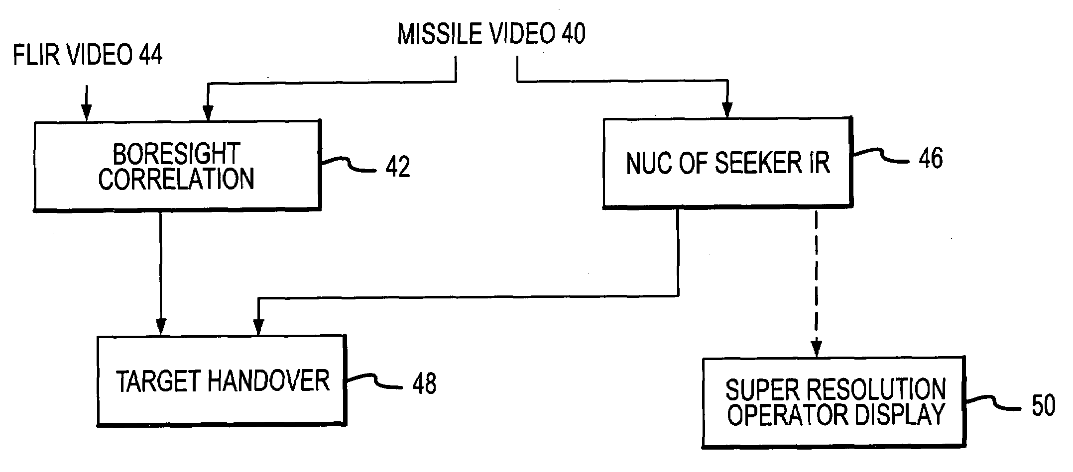
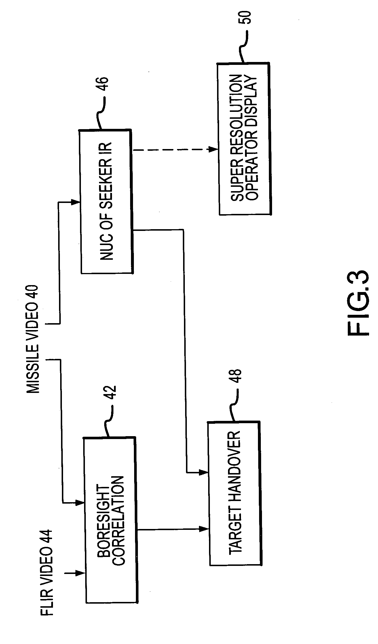
[0031]As shown in FIG. 3, this is accomplished in part with a method that performs boresight correlation with un-NUCed missile video 40. This allows boresight correlation 42 with the FLIR video 44 and NUC 46 on the missile video 40 to be performed simultaneously thereby reducing the time required to perform target handover 48 from the FLIR to the missile seeker and fire the missile. NUC is not required for target handover, however it is useful to improve the SNR of the missile video. The NUC process also provides the capability of displaying enhanced, e.g., noise filtered and super resolved, imagery on an operator display 50.

[0032]The current approach to boresight correlation temporally processes the missile video from the IR imager to locate edges in an IR image, spatially processes the FLIR video in acc...


PUM


Abstract

The present invention provides for simple and streamlined boresight correlation of FLIR-to-missile video. Boresight correlation is performed with un-NUCed missile video, which allows boresight correlation and NUC to be performed simultaneously thereby reducing the time required to acquire a target and fire the missile. The current approach uses the motion of the missile seeker for NUCing to produce spatial gradient filtering in the missile image by differencing images as the seeker moves. This compensates DC non-uniformities in the image. A FLIR image is processed with a matching displace and subtract spatial filter constructed based on the tracked scene motion. The FLIR image is resampled to match the missile image resolution, and the two images are preprocessed and correlated using conventional methods. Improved NUC is provided by cross-referencing multiple measurements of each area of the scene as viewed by different pixels in the imager. This approach is based on the simple yet novel premise that every pixel in the array that looks at the same thing should see the same thing. As a result, the NUC terms adapt to non-uniformities in the imager and not the scene.

Description

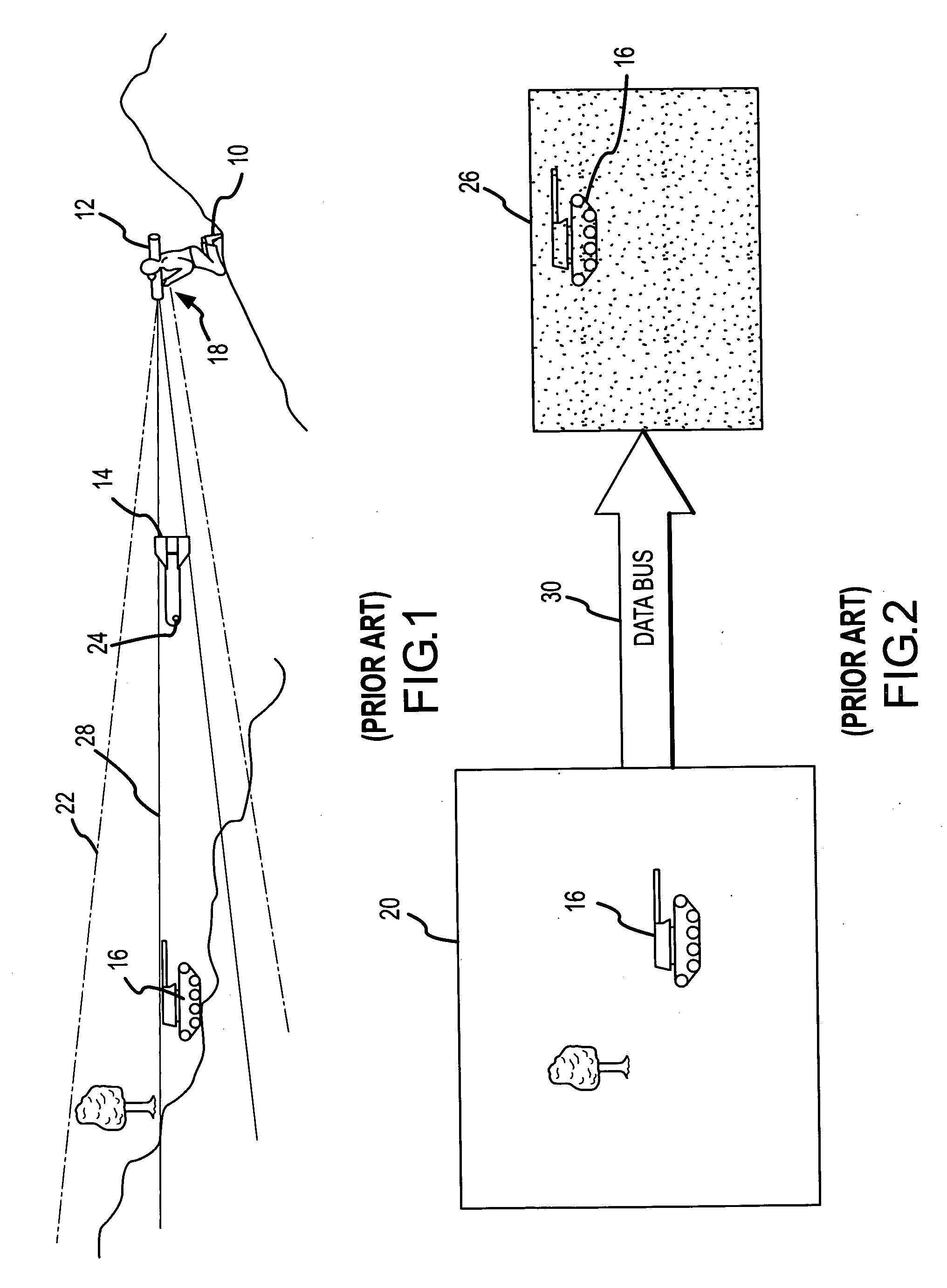
BACKGROUND OF THE INVENTION[0001]1. Field of the Invention[0002]This invention relates to the boresight correlation and non-uniformity compensation that must occur before target handover from the FLIR to the missile seeker, and more specifically to a method of correlating un-NUCed missile video to the FLIR and an improved scene based method of non-uniformity compensation.[0003]2. Description of the Related Art[0004]In guided missile systems, certain calibrations must be performed before target handover from the target designation device such as a forward looking infrared (FLIR) to the missile seeker. These include performing a boresight correlation to correct for any imprecise mechanic alignments between the FLIR and missile seeker and performing a non-uniformity compensation to reduce pixel-to-pixel response non-uniformities in the seeker's IR imager. These adjustments improve the missile's chance of acquiring and then tracking the target to impact.[0005]As shown in FIGS. 1 and 2, ...

Claims


Application Information

Patent Timeline
IPC IPC(8): G06K9/00G01P3/36F42B15/01
CPCF41G7/007F41G7/2226F41G7/2253H04N5/3656G01S3/7803H04N5/33F41G7/2293H04N25/674
Inventor WILLIAMS, DARIN S,KITCHEN, EDWARD N.
Owner RAYTHEON CO
Learn More