Rotor system with pitch flap coupling

a technology of rotor blades and couplings, which is applied in the field of servoflap rotor blade systems, can solve the problems of relatively simple rotor system response, relatively slow rotor system response, and relatively complicated incorporation of pitch-flap coupling subsystems

Active Publication Date: 2008-05-15
SIKORSKY AIRCRAFT CORP
View PDF5 Cites 68 Cited by
  • Summary
  • Abstract
  • Description
  • Claims
  • Application Information

AI Technical Summary

Benefits of technology

[0009]In operation, since the elastomeric spherical bearing focal point is located inboard of the servo-flap pitch control tube pivot point, and the blade servo-flap pitch control tube is free to tilt relative to the blade retention spindle as the blade flaps, a stabilizing pitch-flap coupling can be generated. That is, during blade flapping, relative vertical and radial motions occur between the blade servo-flap pitch control tube and the blade retention spindle. These relative vertical and radial motions drive the servo-flap drive linkage to pitch the servo-flap relative the rotor blade. Flapping up produces a tension in the push / pull link to pitch the servo-flap up which thereby provides a pitch-down movement in the rotor blade.

Problems solved by technology

The rotor systems for rotary-wing aircraft such as helicopters and tilt rotor aircraft are relatively complex systems.
Large flapwise loads may cause pitch changes in the rotor blades such that rotor system response may become relatively sluggish, i.e., counteracts cyclic inputs.
In a fully articulated servo-flap rotor system, there is no direct control link to the rotor blades such that incorporation of a pitch-flap coupling (Delta-3) subsystem may be relatively complicated.

Method used


Image

  • Rotor system with pitch flap coupling
  • Rotor system with pitch flap coupling
  • Rotor system with pitch flap coupling

Examples


Embodiment Construction

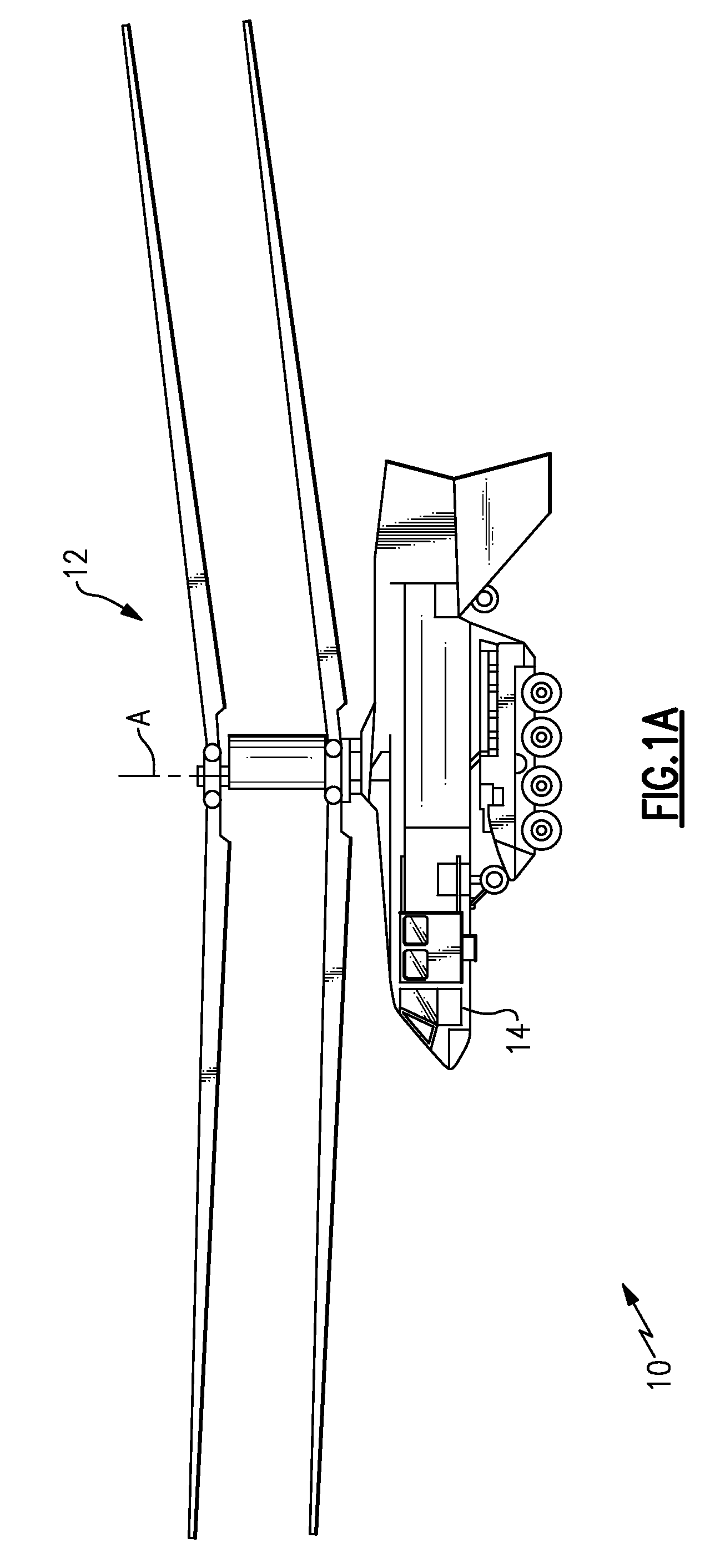
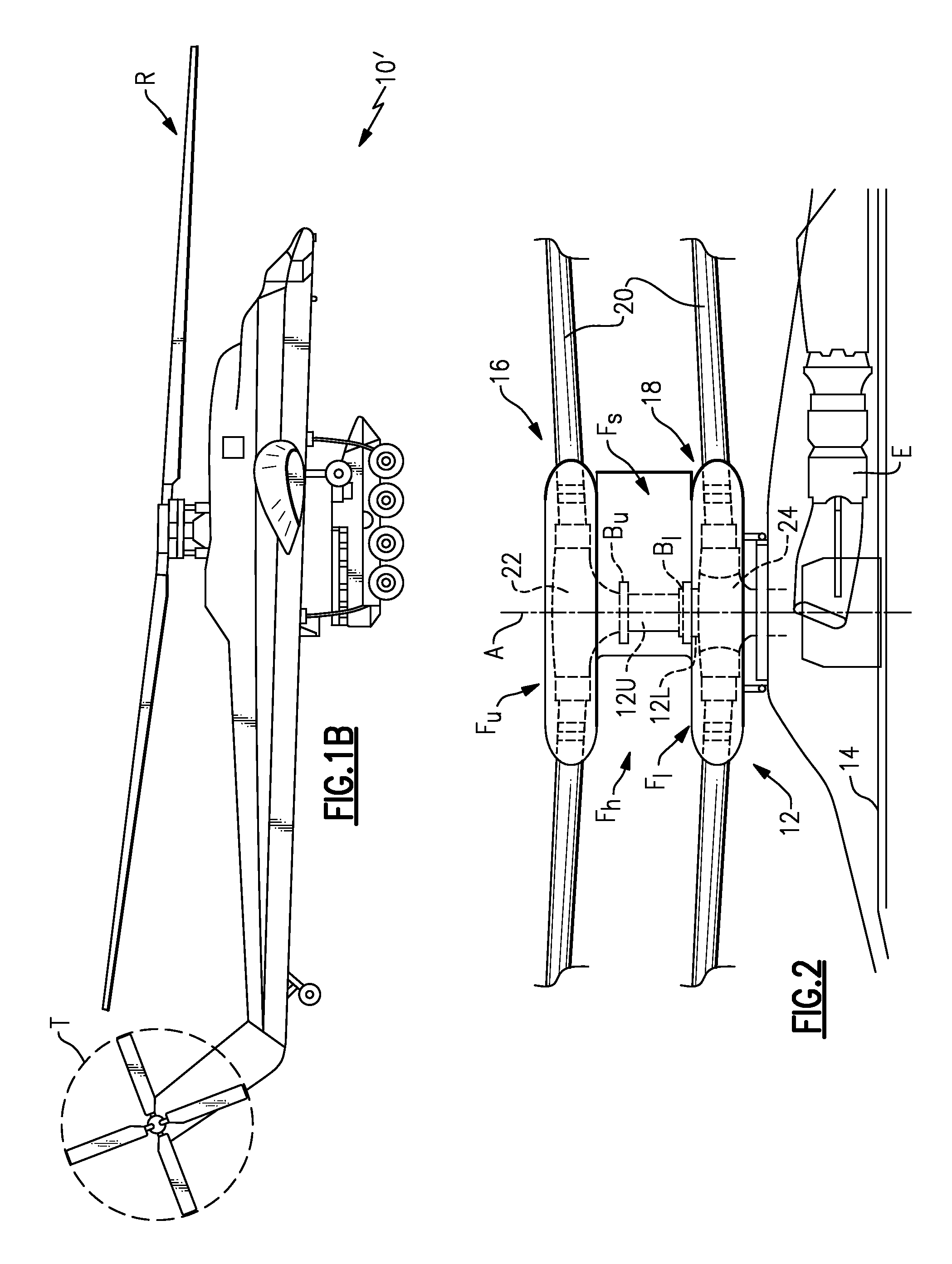
[0029]FIG. 1A illustrates an exemplary vertical takeoff and landing (VTOL) rotary-wing aircraft 10 having a dual, counter-rotating, coaxial rotor system 12 which rotates about an axis of rotation A. The aircraft 10 includes an airframe 14 which supports the dual, counter rotating, coaxial rotor system 12. Although a particular type rotary-wing aircraft configuration is illustrated in the disclosed embodiment, other aircraft such as single rotor flying crane helicopters 10′ having a single main rotor assembly R and an anti-torque rotor T mounted to an extended tail (FIG. 1B), tilt-rotor and tilt-wing aircraft which utilize a servo-flap rotor control system will also benefit from the present invention.

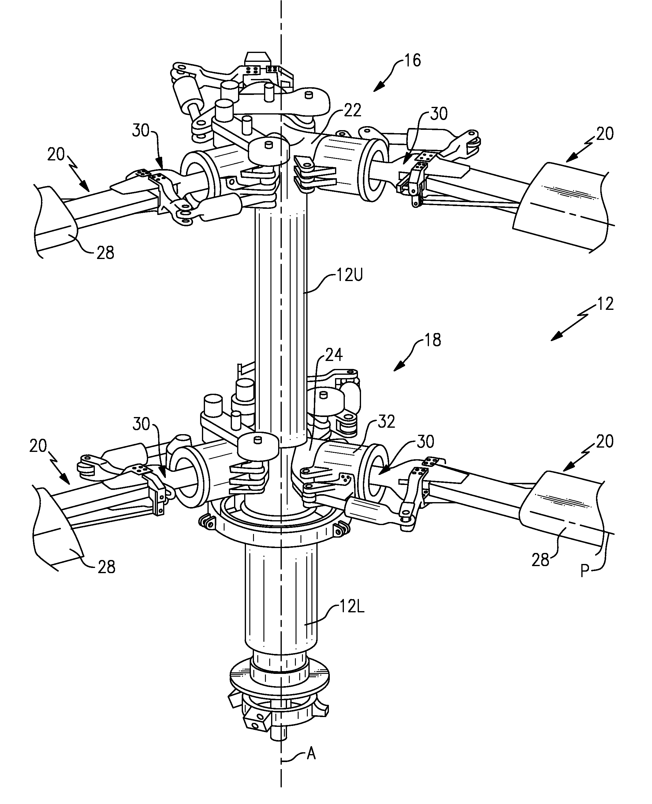
[0030]Referring to FIG. 2, the dual, counter-rotating, coaxial rotor system 12 includes an upper rotor system 16 and a lower rotor system 18. Each rotor system 16, 18 includes a plurality of rotor blade assemblies 20 mounted to a rotor hub assembly 22, 24 for rotation about the rotor axi...


PUM


Abstract

An articulated rotor system with a servo-flap rotor control system locates the focal point of a blade retention spherical elastomeric bearing inboard of a joint in the servo-flap pitch control tube which separates the flap hinge and supports the servo-flap pitch control tube on a single pivot bearing within a blade retention spindle. Rotor blade flapping produces relative movements between the servo-flap pitch control tube and the blade retention spindle which is converted through a servo-flap drive linkage into servo-flap pitch motions to provide flap/pitch coupling which reduces steady and transient blade flapping.

Description

BACKGROUND OF THE INVENTION[0001]The present invention relates to a servo-flap rotor blade system of a rotary-wing aircraft, and more particularly to a servo-flap rotor blade system with an adjustable pitch / flap coupling.[0002]The rotor systems for rotary-wing aircraft such as helicopters and tilt rotor aircraft are relatively complex systems. The rotor system needs to respond to the pilot's input, but also needs to accommodate forces acting upon the rotor system which may be generally outside of direct pilot control.[0003]In a fully articulated rotor system, each individual rotor blade is attached to the rotor hub such that the rotor blade may pitch, lead / lag and flap. Blade pitch is generally under direct management by the pilot through the flight control system. Lead / lag and flapping motion, however, are generally not under the pilot's direct control as these motions are in response to forces from the constantly changing balance between lift, centrifugal, and inertial forces for ...

Claims


Application Information

Patent Timeline
Patent Type & Authority Applications(United States)
IPC IPC(8): B64C11/06
CPCB64C27/10B64C27/615B64C27/35B64C2027/7294B64C27/32Y02T50/34Y02T50/30
Inventor SCHMALING, DAVID N.CABRERA, PEDRO L.
Owner SIKORSKY AIRCRAFT CORP
Why Eureka
Try Eureka