Power Scheme for Implant Stimulators on the Human or Animal Body

a technology of implant stimulators and power schemes, which is applied in the field of implant stimulators for humans or animals, can solve the problems of large prosthetic devices, large bulky, and insufficient simulated vision to truly aid the visually impaired, and achieve the effect of reducing power delivering efficiency and reducing the size of the devi

Active Publication Date: 2008-05-15
CORTIGENT INC
View PDF14 Cites 12 Cited by
  • Summary
  • Abstract
  • Description
  • Claims
  • Application Information

AI Technical Summary

Benefits of technology

[0024]According to a sixth aspect of the present disclosure, a method to control power in an implant for a human or animal body is shown, the implant comprising electrodes contacting a tissue of the body, the method comprising: capacitively storing electric charges; providing the electric charges to the electrodes; monitoring when the electric charges are above a high value or below a low value; and controlling the electric charges when above the high value or below the low value.
[0025]According to a seventh aspect of the present disclosure, a circuit is shown, comprising: an electrode driver array; storage capacitors connected with the electrode driver array, wherein charge stored on the storage capacitors is adapted to be transferred to an array of electrodes connected with the electrode driver array; a charging circuit charging the storage capacitors; and a monitoring circuit to continuously monitor voltage on the storage capacitors and to control at least one between the electrode driver array and the charging circuit based on the voltage.

Problems solved by technology

While some of these early attempts met with some limited success, these early prosthetic devices were large, bulky and could not produce adequate simulated vision to truly aid the visually impaired.
When the coil sizes and positioning are limited by the physical conditions, the power delivering efficiency can be reduced dramatically, in which case the maximum power to the implant may be limited.
On the other hand, a higher amount of power used by the implant also means a worse condition in terms of thermal dissipation.

Method used


Image

  • Power Scheme for Implant Stimulators on the Human or Animal Body
  • Power Scheme for Implant Stimulators on the Human or Animal Body
  • Power Scheme for Implant Stimulators on the Human or Animal Body

Examples


Embodiment Construction

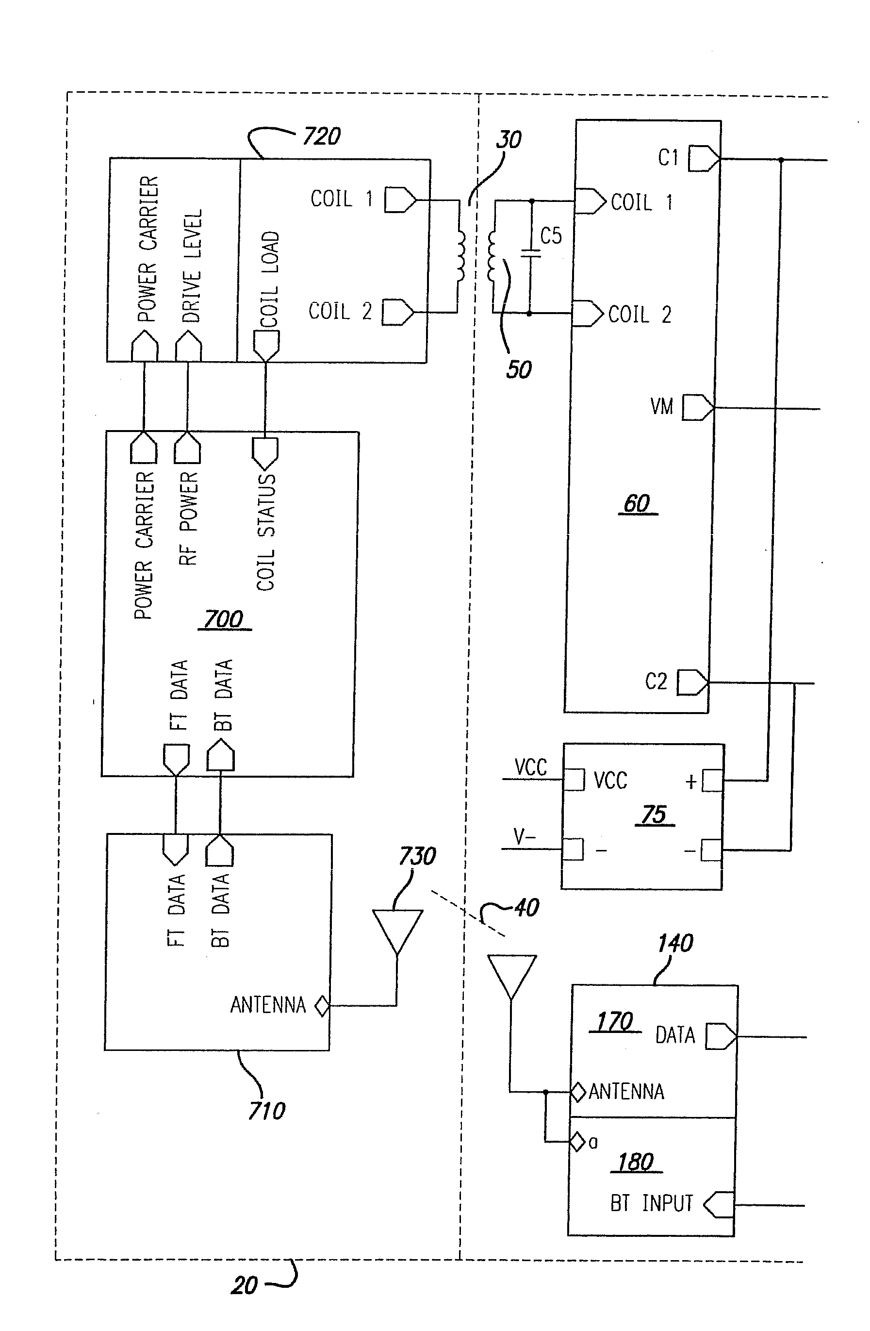
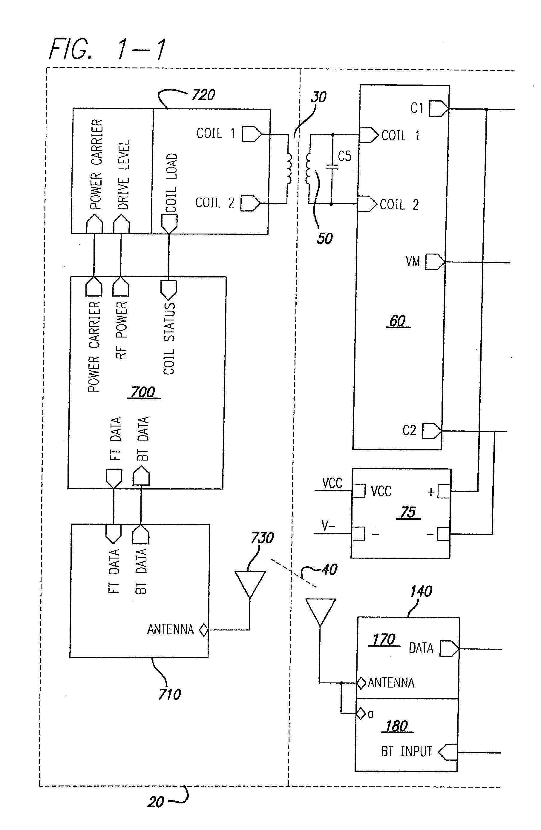
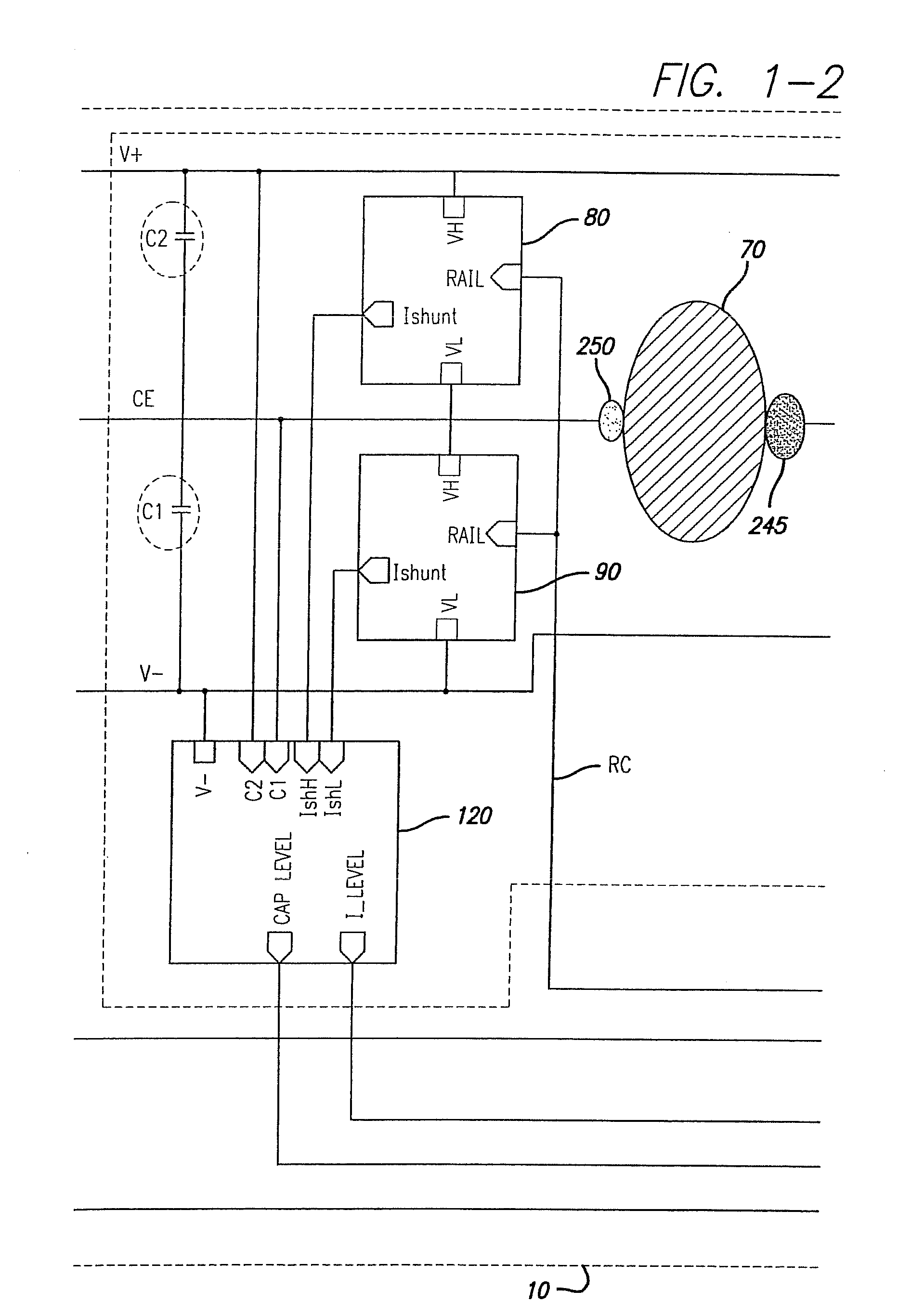
[0034]FIGS. 1-1, 1-2 and 1-3 are a diagram of an implant power control scheme in accordance with an embodiment of the present disclosure.

[0035]A retinal implant 10 receives power from an external unit 20 through an inductive power link 30 coupled through coils. Control and status information are exchanged between retinal implant 10 and external unit 20 through data link 40. While the embodiment of FIGS. 1-1, 1-2, 1-3 and the following figures is concerned with a retinal implant, the person skilled in the art will appreciate that the same scheme can be used also for other types of implants on the human or animal body, such as cochlear implants or implants to restore neuronal functions impaired due to injuries or diseases.

[0036]Power at the implant side is received by implant coil 50. Implant coil 50 is tunable with capacitor C3 to the power carrier frequency. The received AC power is converted into DC power by a rectifier circuit 60. Rectifier circuits are known per se to the person ...


PUM


Abstract

A power scheme for an implant on a human or animal body comprises: a charging circuit to provide power to deliver controlled stimulation currents to a body tissue; a capacitive storage arrangement connected with the charging circuit and charged by the charging circuit; a shunting arrangement to limit voltage on the capacitive storage arrangement; a driver array configured to transfer charges from the capacitive storage arrangement to the tissue; and an electrode array connected with the driver array and the tissue.

Description

CROSS REFERENCE TO RELATED APPLICATIONS[0001]This application is a divisional application of, and claims priority to, U.S. application Ser. No. 11 / 598,965, filed Nov. 14, 2006, for Power Scheme for Implant Stimulators on the Human or Animal Body.FEDERALLY SPONSORED RESEARCH[0002]This invention was made with government support under grant No. R24EY12893-01, awarded by the National Institutes of Health. The U.S. Government may have certain rights in the invention.BACKGROUND[0003]1. Field[0004]The present disclosure relates to implants for humans or animals. In particular, it relates to a power scheme for implant stimulators (also referred to as implants in the present application) on the human or animal body.[0005]2. Related Art[0006]The following paragraphs will introduce some art possibly related to the present application.[0007]In 1755 LeRoy passed the discharge of a Leyden jar through the orbit of a man who was blind from cataract and the patient saw “flames passing rapidly downwa...

Claims


Application Information

Patent Timeline
Patent Type & Authority Applications(United States)
IPC IPC(8): A61B5/042A61N1/05
CPCA61N1/378A61N1/36046
Inventor DAI, RONGQINGGREENBERG, ROBERT J.
Owner CORTIGENT INC
Why Eureka
Try Eureka