Showcase

Active Publication Date: 2008-05-22
SANYO ELECTRIC CO LTD
View PDF7 Cites 15 Cited by
  • Summary
  • Abstract
  • Description
  • Claims
  • Application Information

AI Technical Summary

Benefits of technology

[0021]According to the present invention, the plural fins of the cooler are constructed by the long fins and the short fins which are different in length in the air flow direction, the projecting portions are formed at the edge portions of the hole portions through which the refrigerant pipe is inserted, and the short fins are arranged between the long fins at the downstream side with respect to the air flow direction so that the projecting portion of each short fin abuts against the adjacent long or short fin to thereby form the gaps between the plural fins. Therefore, the interval between the long fins located at the upstream side with respect to the air flow direction can be settled to one value on the basis of the length of the projecting portions of the short fins located at the downstream side with respect to the air flow direction. Therefore, by assembling the fins while the projecting portions of the short fins located at the downstream side abut against the adjacent fins, the interval between the long fins located at the upstream side can be kept to a predetermined interval without using any special jig for keeping the interval between the long fins. Accordingly, the number of steps of the fabrication process

Problems solved by technology

Particularly when the gap between the neighboring fins is small, the gap portion is supercooled and thus the fins are liable to be frosted.
Therefore, it is difficult to set the projection length of the projecting portions formed by the burring method to a predetermined length or more.
Particularly when the straight portions of the plural hair pins are locally densely arranged, the gap between these portions is small and thus air passing through

Method used


Image

  • Showcase
  • Showcase
  • Showcase

Examples


Embodiment Construction

[0032]Preferred embodiments according to the present invention will be described hereunder with reference to the accompanying drawings.

[0033]A showcase according to an embodiment of the present invention will be described.

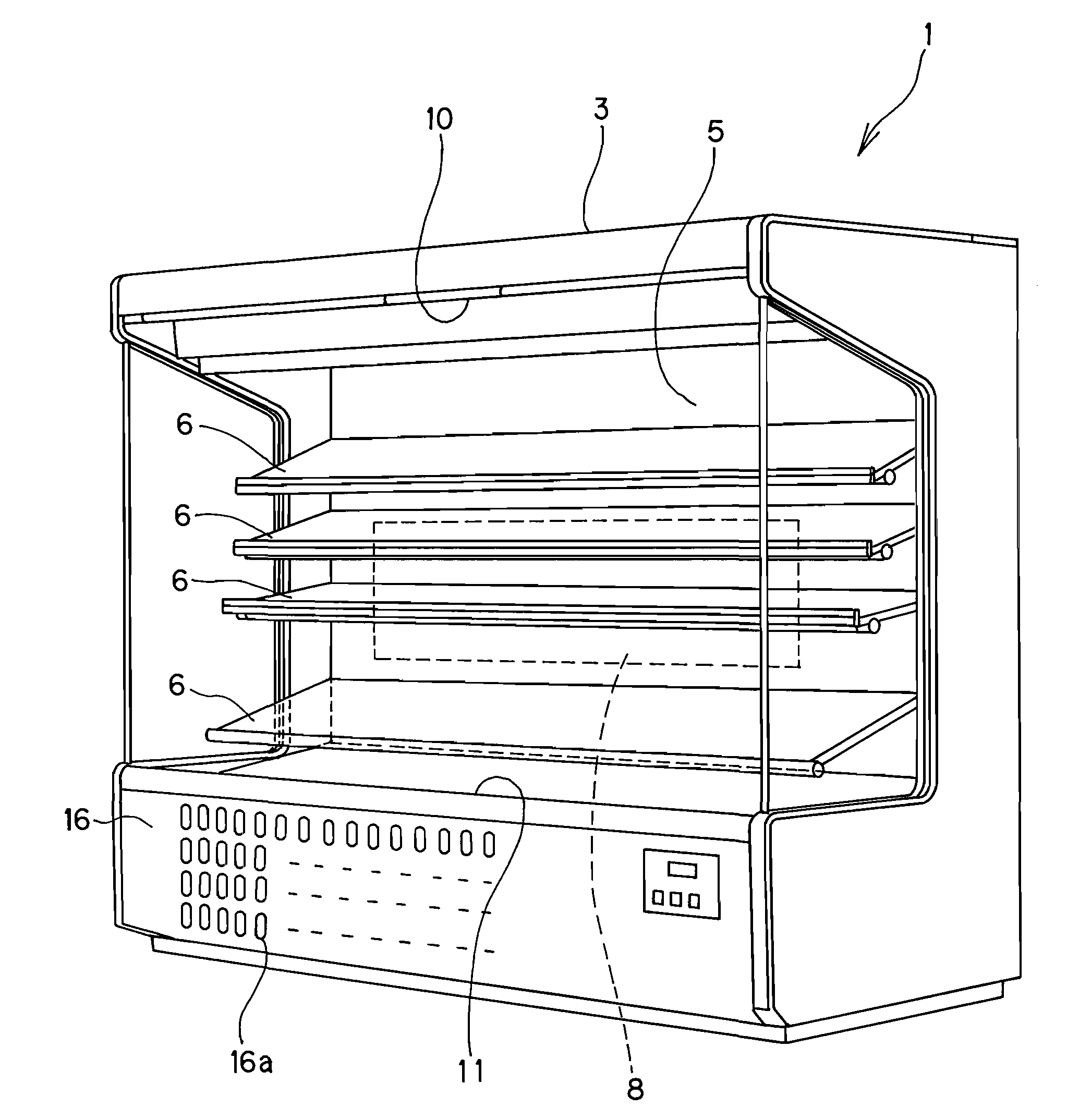
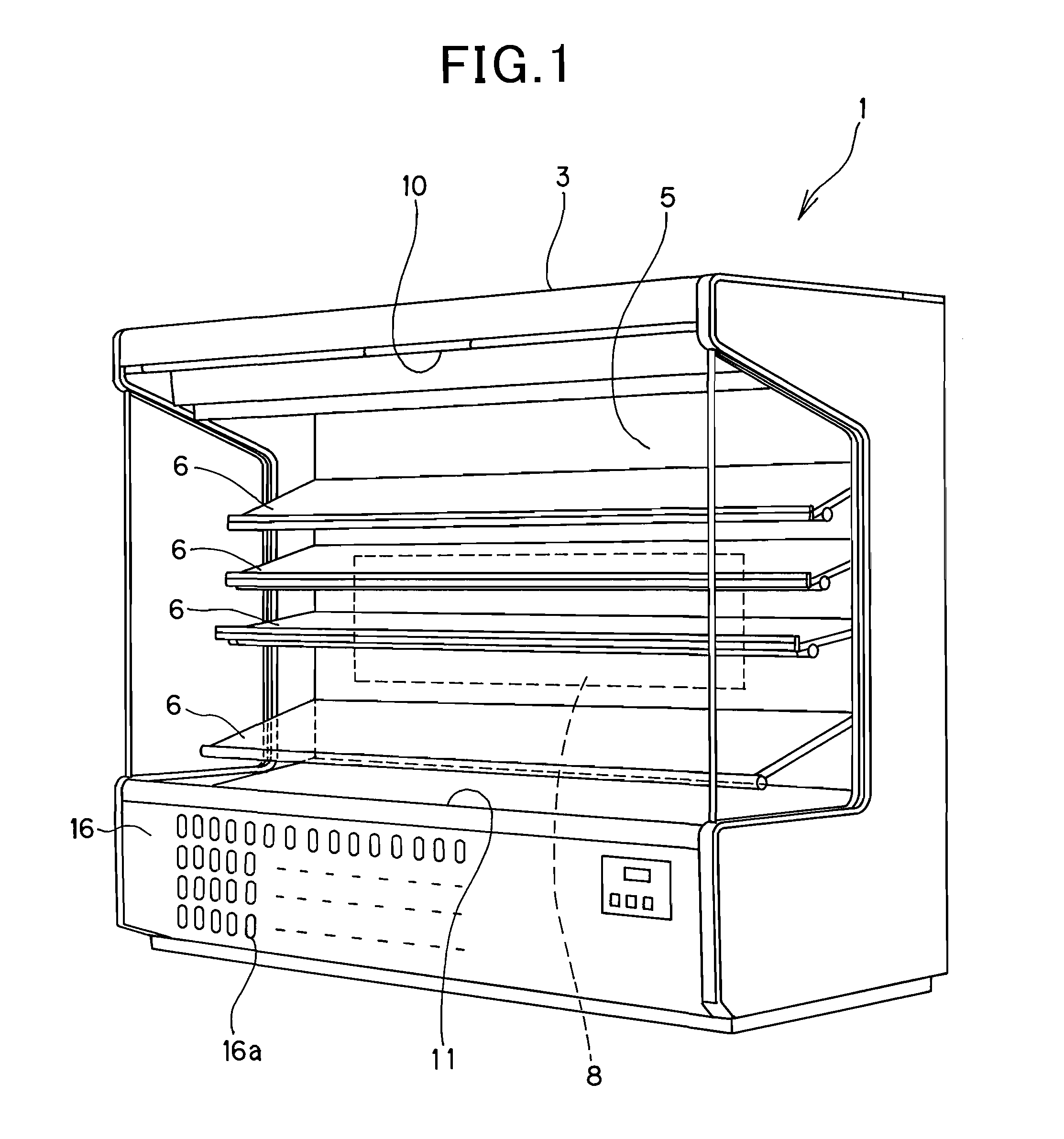
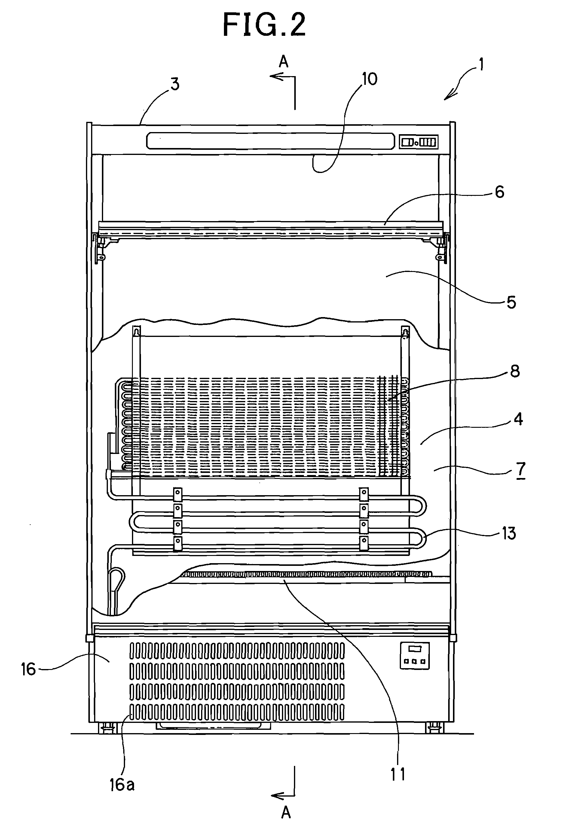
[0034]FIG. 1 is a perspective view when the showcase of the embodiment is viewed from the oblique right side in front of the showcase. FIG. 2 is a front view of the showcase and the inner wall portion is partially cut out. FIG. 3 is a side cross-sectional view which is taken along A-A line of FIG. 2. The directions used in the following description of the embodiments are defined with respect to FIG. 2 so that the up and down directions on the sheet surface are set to the up and down directions of the showcase, the right and left directions on the paper surface are set to the right and left directions of the showcase and the depth direction on the paper surface is set to the forward and rearward directions of the showcase.

[0035]The showcase 1 according to this embod...


PUM


Abstract

A showcase having a fin-and-tube type cooler which comprises plural planar fins and a refrigerant pipe penetrating through the plural planar fins and cools air to be fed toward display racks, wherein the plural planar fins comprise long fins arranged in parallel to an air flow direction along which air flows through the cooler, and short fins that are shorter in length in the air flowing direction than the long fins and arranged between respective adjacent long fins at the downstream side of the cooler with respect to the air flowing direction. Furthermore, the refrigerant pipe comprises first U-shaped hair pins each having two straight pipe portions and second U-shaped hair pins each having two straight pipe portions, the pitch between the two straight pipe portions of each second U-shaped hair pin is set to the double of the pitch between the two straight pipe portions of each first U-shaped hair pin, and the first and second U-shaped hair pins penetrate through the hole portions formed in the plural planar fins so as to be disposed in a predetermined arrangement style.

Description

INCORPORATION BY REFERENCE[0001]The present application claims priority under 35 U.S.C. § 119 to Japanese Patent Application Nos. 2006-314144 and 2006-314145 filed on Nov. 21, 2006. The contents of the applications are incorporated herein by reference in its entirety.BACKGROUND OF THE INVENTION[0002]1. Field of the Invention[0003]The present invention relates to a showcase for storing foods, etc. under the state that the foods, etc. are kept fresh for a long term to sell the foods, etc. in a store.[0004]2. Description of the Related Art[0005]In a supermarket or a convenience store is placed a showcase which is opened at the front side thereof so that purchasers can easily pick up foods, etc. to be sold (for example, dressed meat, fresh fish, frozen foods, ice cream, etc.). A cooler is provided in such a showcase, and there is known a so-called fin-and-tube type cooler in which plural fins are arranged in alignment with one another so as to be spaced from one another at predetermined...

Claims


Application Information

Patent Timeline
IPC IPC(8): F28F1/42F28F1/10
CPCA47F3/0443F25B39/02F25B2309/061F28F2215/04F25D21/04F28D1/0477F28F1/32F25B2500/01
Inventor UCHIDA, TOMOHIROTAMURA, TOSHIYUKIYANAGI, HIROFUMI
Owner SANYO ELECTRIC CO LTD
Why Eureka
Try Eureka