Eureka AIR delivers breakthrough ideas for toughest innovation challenges, trusted by R&D personnel around the world.

Voltage rising/falling type switching regulator and operation control method thereof

Inactive Publication Date: 2008-05-22
RICOH KK
View PDF9 Cites 10 Cited by
  • Summary
  • Abstract
  • Description
  • Claims
  • Application Information

AI Technical Summary

Benefits of technology

[0014]According to one aspect of the invention there is disclosed a voltage rising / falling type switching regulator and its operation control method which is capable of reducing effectively the fluctuation of the output voltage at the time of switching between voltage falling operation and voltage rising operation, without causing the non-control state to occur.
[0037]According to embodiments of the voltage rising / falling type switching regulator and its operation control method of the invention, at the time of shifting from voltage rising operation to voltage falling operation and / or at the time of shifting from voltage falling operation to voltage rising operation, the switching transistor for voltage rising and the switching transistor for voltage falling are synchronized and a voltage rising / falling operation which is turned on in a 50% duty cycle is performed. Accordingly, without causing the non-control state to occur, it is possible to reduce effectively the fluctuation of the output voltage at the time of switching between voltage falling operation and voltage rising operation. Since the frequency of each of the triangular wave signal for voltage falling operation, the triangular wave signal for voltage rising operation and triangular wave signal for voltage rising / falling operation is constant, it is possible to avoid the occurrence of noises in various frequency bands.

Problems solved by technology

However, the switching regulator of Japanese Laid-Open Utility Model Application No. 6-70486 has a problem in that when the switching regulator is in the non-control state, both the switching transistor for voltage falling and the switching transistor for voltage rising stop operation, and the power conversion efficiency improves.
However, at the time of shifting from voltage falling operation or voltage rising operation to the non-control state, or at the time of shifting from the non-control state to voltage falling operation or voltage rising operation, the power loss changes abruptly and the output voltage Vo fluctuates sharply.
Thus, there is a problem that the cost for the adjustment of the resistance increases.
In the operation control method of Japanese Laid-Open Patent Application No. 2003-125576, the clock frequency of the converter changes according to the input voltage, and it is likely that noises occur over a wide range of frequencies.
Thus, the operation control method is not appropriate for use in power supplies of wireless communication devices or the like.

Method used


Image

  • Voltage rising/falling type switching regulator and operation control method thereof
  • Voltage rising/falling type switching regulator and operation control method thereof
  • Voltage rising/falling type switching regulator and operation control method thereof

Examples


Embodiment Construction

[0046]A description will be given of embodiments of the invention with reference to the accompanying drawings.

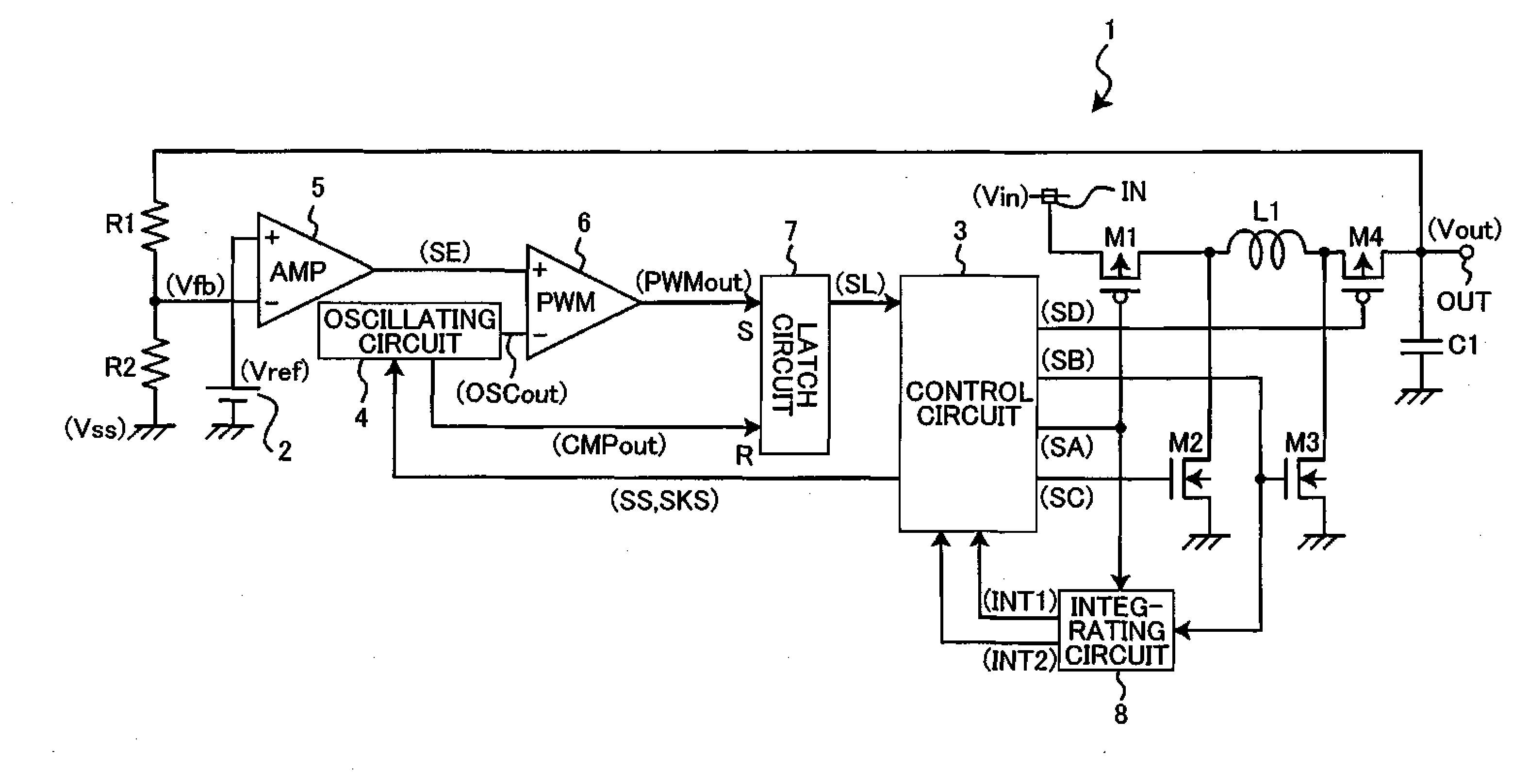
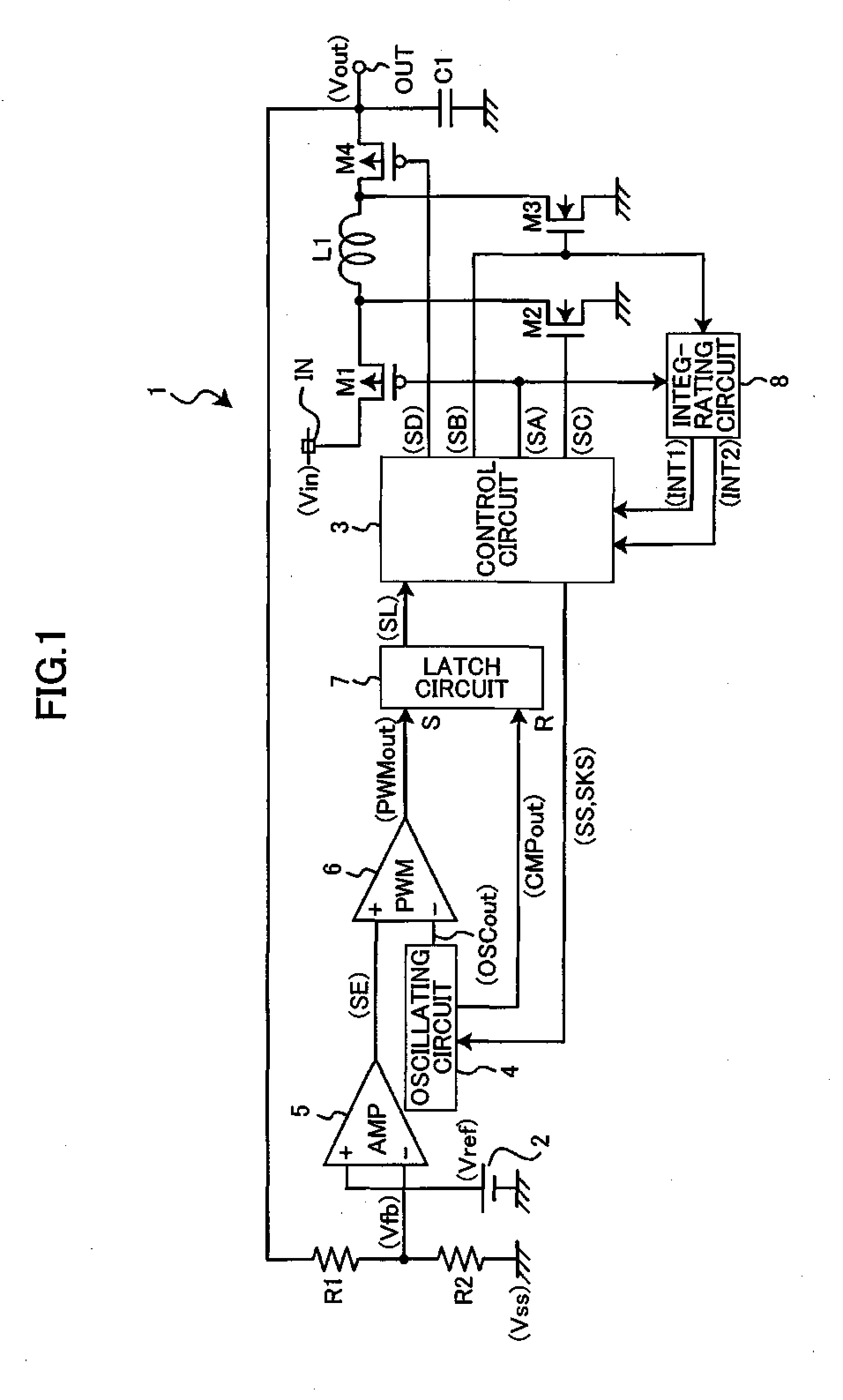
[0047]FIG. 1 shows the circuit composition of a voltage rising / falling type switching regulator in an embodiment of the invention. The voltage rising / falling type switching regulator 1, shown in FIG. 1, is a switching regulator of synchronous rectification type which automatically raises or lowers an input voltage Vin, inputted to an input terminal IN, and converts the input voltage Vin to a predetermined constant voltage, to output the constant voltage from an output terminal OUT as an output voltage Vout.

[0048]The voltage rising / falling type switching regulator 1 includes a switching transistor M1 for voltage falling, a synchronous rectification transistor M2 for voltage falling, a switching transistor M3 for voltage rising, and a synchronous rectification transistor M4 for voltage rising. The switching transistor M1 for voltage falling is formed by a PMOS transistor which...


PUM


Abstract

In a voltage rising / falling type switching regulator including a voltage rising / falling part and a control part, the voltage rising / falling part includes a switching transistor for voltage falling, a rectifier element for voltage falling, a switching transistor for voltage rising, and a rectifier element for voltage rising, the control part is arranged so that the switching transistor for voltage rising and the switching transistor for voltage falling are synchronized at a time of shifting from voltage rising operation to voltage falling operation and / or at a time of shifting from voltage falling operation to voltage rising operation, to perform voltage rising / falling operation in which each switching transistor is turned on in a 50% duty cycle.

Description

BACKGROUND OF THE INVENTION[0001]1. Field of the Invention[0002]This invention relates to a voltage rising / falling type switching regulator and its operation control method in which voltage rising / falling operations are switched automatically, and more particularly to operation of a switching regulator at a time of switching voltage rising operation and voltage falling operation.[0003]2. Description of the Related Art[0004]FIG. 6 shows a voltage rising / falling type switching regulator according to the related art (for example, Japanese Laid-Open Utility Model Application No. 6-70486). FIG. 7 shows the relationship between input voltage Vi and output voltage Vo in the voltage rising / falling type switching regulator of FIG. 6.[0005]In the voltage rising / falling type switching regulator of FIG. 6, at a time of voltage falling operation, a voltage falling control circuit 101 controls the on-duty cycle of a pulse inputted to the base of a switching transistor Q101 for voltage falling, so...

Claims


Application Information

Patent Timeline
IPC IPC(8): G05F1/10
CPCH02M3/1582H02M3/155
Inventor NISHIDA, JUNJI
Owner RICOH KK
Why Eureka
Eureka Blog
Learn More