
Testing system contactor

a technology of contactor and system, applied in the direction of individual semiconductor device testing, material flaw investigation, instruments, etc., can solve the problems of incorrect temperature calibration error calculation, insufficient precise value of actual temperature (and temperature of integrated circuit), and inability to accurately test and trim an integrated circuit. , to achieve the effect of eliminating errors in testing, reducing the number of steps required, and accurately testing and trimming an integrated circui

Active Publication Date: 2008-05-22
ANALOG DEVICES INC
View PDF10 Cites 28 Cited by
  • Summary
  • Abstract
  • Description
  • Claims
  • Application Information

AI Technical Summary

Benefits of technology

[0011]It is a further object of this invention to provide such a contactor which eliminates errors in testing.
[0012]It is a further object of this invention to provide such a contactor which reduces the number of steps required to accurately test and trim an integrated circuit.
[0013]It is a further object of this invention to provide such a contactor which is able to determine a predictable thermal path from the heat source through the test chuck to the device under test.
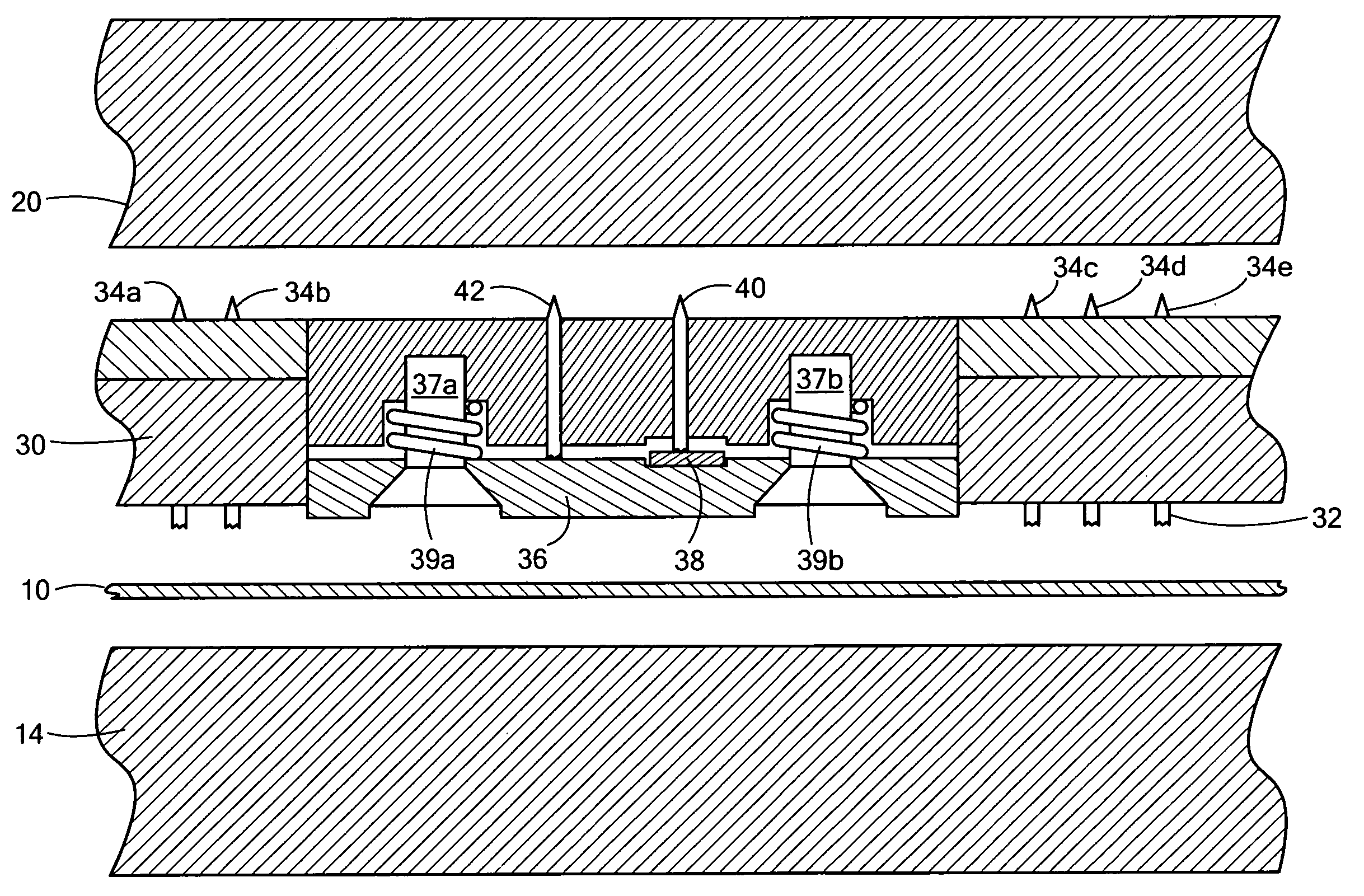
[0014]The subject invention results from the realization in part that an improved contactor includes an integrated temperature sensor to more directly measure the temperature of a device under test to determine if the device is correctly seated in the test chuck and to eliminate errors associated with testing and trimming the device.

Problems solved by technology

If a golden strip is not seated correctly, the temperature calibration errors calculated are incorrect.
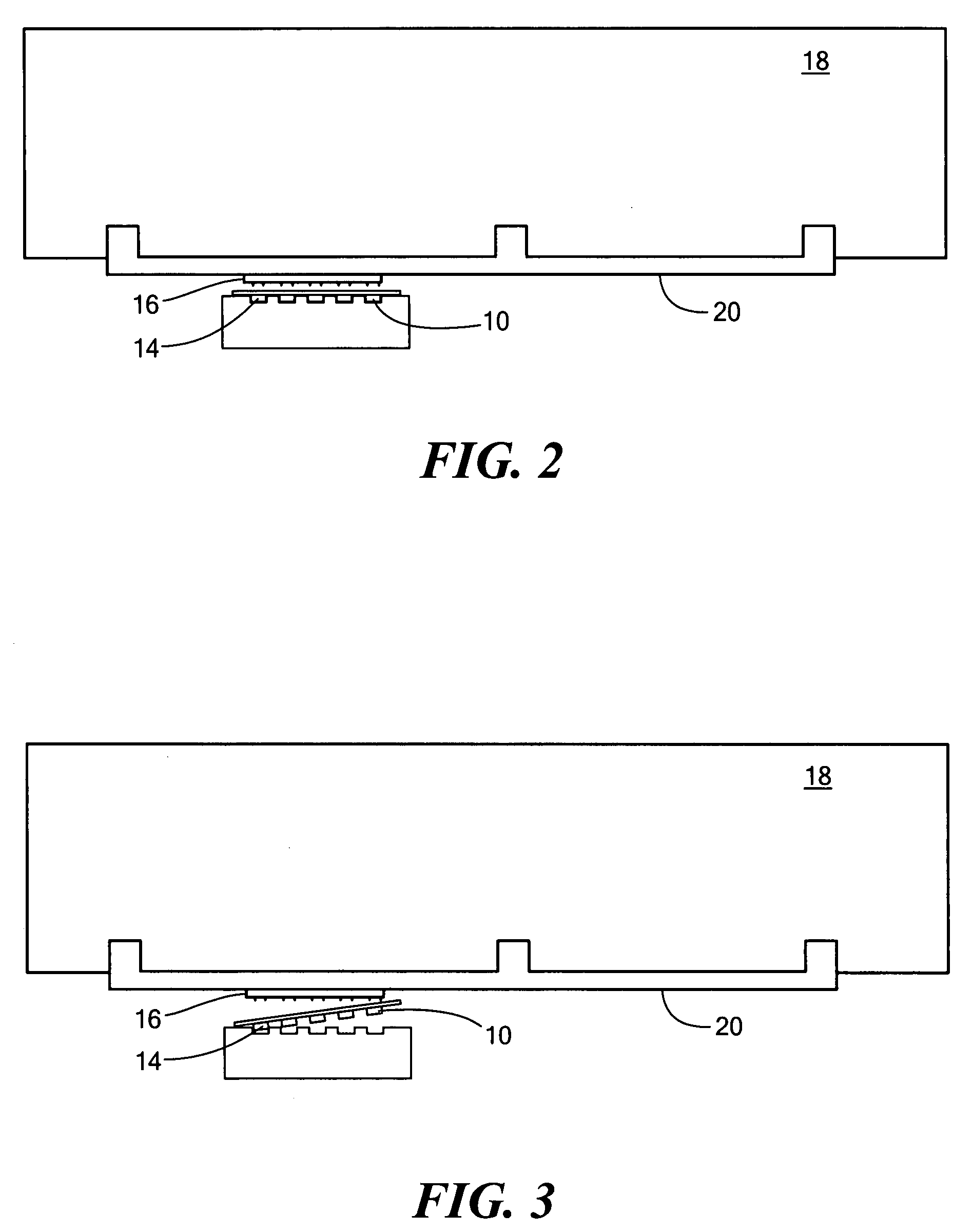
If the integrated circuit is not correctly positioned in the test chuck, it is not heated properly to the correct value and the result will be that the integrated circuit is trimmed to the wrong value or values.
Also, even if the integrated circuit is positioned correctly in the test chuck, its actual temperature (and the temperature of the integrated circuit) may not be known to a sufficient precise value.

Method used


Image

  • Testing system contactor
  • Testing system contactor
  • Testing system contactor

Examples


Embodiment Construction

[0039]Aside from the preferred embodiment or embodiments disclosed below, this invention is capable of other embodiments and of being practiced or being carried out in various ways. Thus, it is to be understood that the invention is not limited in its application to the details of construction and the arrangements of components set forth in the following description or illustrated in the drawings. If only one embodiment is described herein, the claims hereof are not to be limited to that embodiment. Moreover, the claims hereof are not to be read restrictively unless there is clear and convincing evidence manifesting a certain exclusion, restriction, or disclaimer.

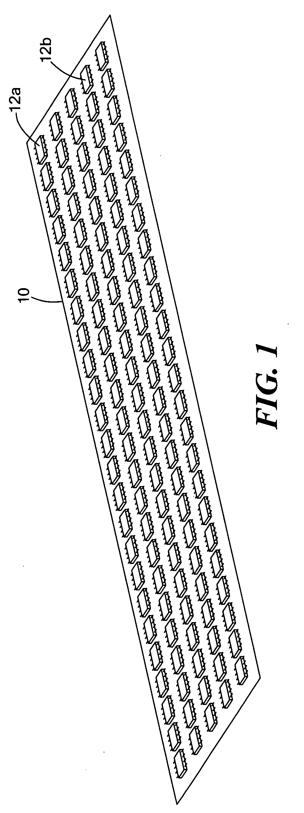
[0040]FIG. 1 shows test strip 10 with an array of integrated circuit chips 12a, 12b, and the like thereon. As shown in FIG. 2, test strip 10 is loaded into test chuck handler 14, an automated device which moves in three axes to test the integrated circuits on strip 10. Contactor 16 in test head 18 is brought into contact wi...


PUM

PropertyMeasurementUnit
distanceaaaaaaaaaa
electrically testaaaaaaaaaa
temperatureaaaaaaaaaa

Abstract

A testing system contactor with an integral temperature measurement sensor.

Description

RELATED APPLICATIONS[0001]This application claims benefit of U.S. Provisional Application No. 60 / 860,038, filed Nov. 20, 2006, entitled “Apparatus to Thermally Sense the DUT Temperature to Insure the Correct Position of the DUT in Strip Test” incorporated by this reference herein.FIELD OF THE INVENTION[0002]This subject invention relates to a testing system contactor.BACKGROUND OF THE INVENTION[0003]Contactors are used to electrically test integrated circuit chips. Typically, a chip is loaded in a test chuck and the contactor makes electrical contact with the chip. A load board is electrically connected to the contactor and provides signals to the contactor and processes signals from the contactor.[0004]U.S. patents and Published patent applications Nos. U.S. Pat. No. 7,042,240; 2005 / 0189957; 2006 / 0164,111; 2006 / 0145718; and U.S. Pat. No. 6,626,682, all incorporated herein by this reference, disclose various integrated circuit (IC) testing devices.[0005]Sometimes, individual ICs are...

Claims


Application Information

Patent Timeline
Patent Type & Authority Applications(United States)
IPC IPC(8): G01R1/02G01N25/72G01R31/26
CPCG01R31/2891
Inventor BLANEY, GERARDGRUBB, JOHNNOLAN, NIALL
Owner ANALOG DEVICES INC
Learn More