Three Dimensional Projection System

a three-dimensional projection and display system technology, applied in the field of display systems, can solve the problems of ineffective methods, difficult to achieve the effect of a display system, and inability to achieve three-dimensional images

Inactive Publication Date: 2008-05-22
TEXAS INSTR INC
View PDF20 Cites 13 Cited by
  • Summary
  • Abstract
  • Description
  • Claims
  • Application Information

AI Technical Summary

Problems solved by technology

One feature that is difficult for a display system to achieve is the perception of a three-dimensional image.
Unfortunately, these methods are not very practical to implement.
Some of the methods are too inefficient, others require too much alignment of multiple modulators in order to increase the brightness of the image to suitable levels.

Method used


Image

  • Three Dimensional Projection System
  • Three Dimensional Projection System
  • Three Dimensional Projection System

Examples


Embodiment Construction

[0016] A new three dimensional display system design and method has been developed that maximizes the efficiency of the system while limiting the number of modulators that are used to create the projected image. The display system uses a scrolling color filter and recycling integrator to maximize the amount of available white light used by the spatial light modulators.

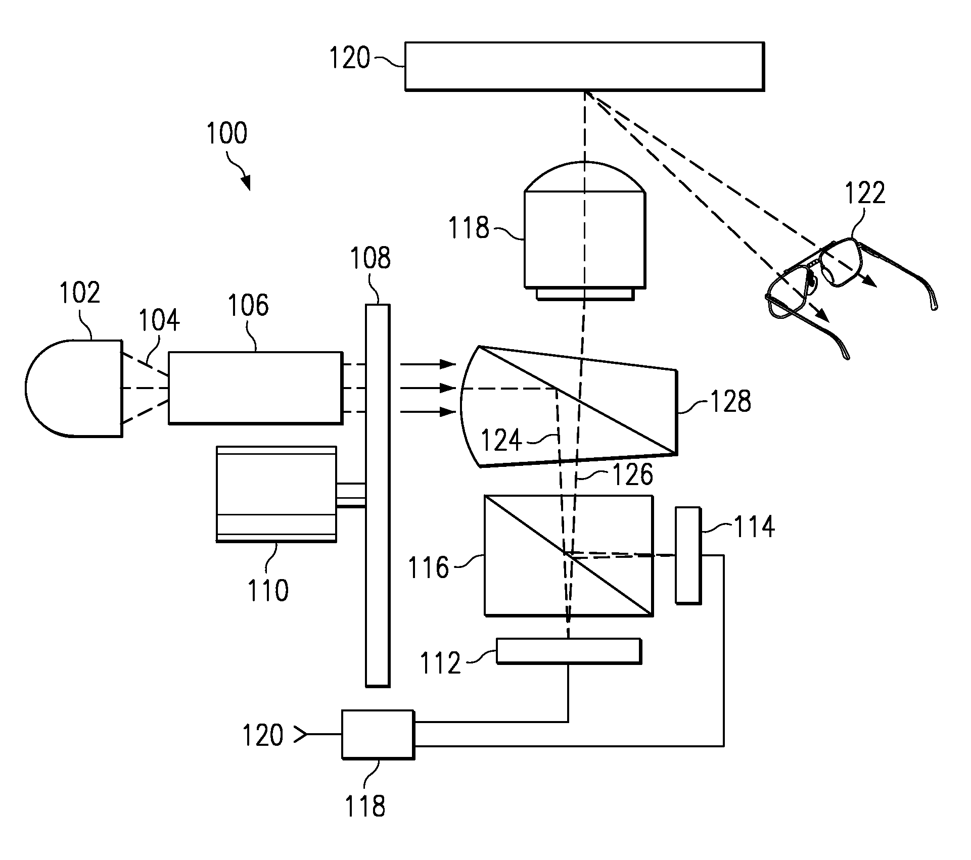
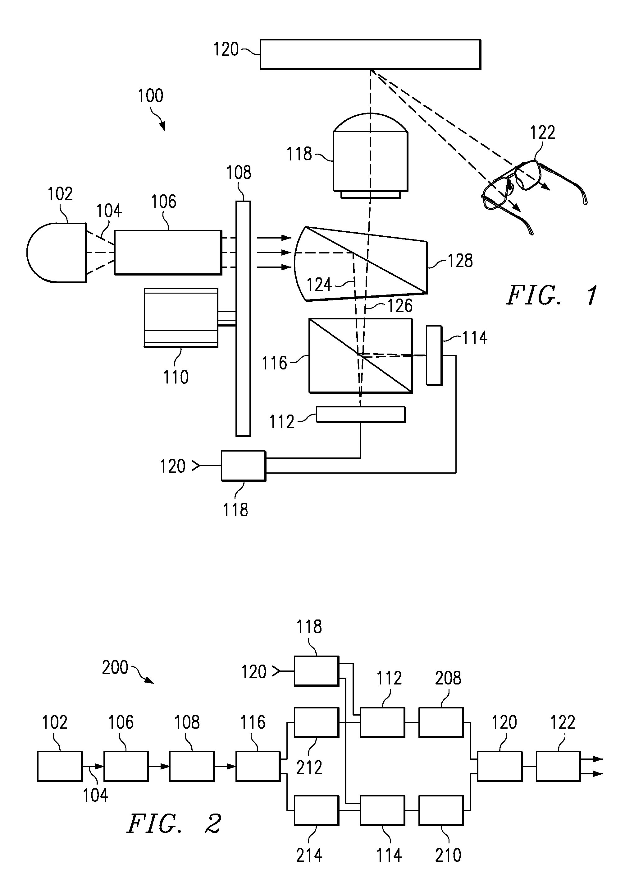
[0017] One embodiment of the three dimensional display system is shown in FIG. 1, which is a schematic view of a three dimensional display system 100 using two spatial light modulators and a single projection path. In FIG. 1, light source 102 emits a white light beam 104 which is focused onto a clear aperture of a recycling integrator 106. The light beam travels through the recycling integrator 106 and is reflected several times by the walls of the integrator 106. The multiple reflections homogenize the light beam giving it a uniform intensity across the width of the beam.

[0018] After leaving the exit end of the inte...


PUM


Abstract

A three dimensional display system 100 using two spatial light modulators and a single projection path. Light source 102 emits a white light beam 104 which is focused onto a clear aperture of a recycling integrator 106. The light beam travels through the recycling integrator 106 and is reflected several times by the walls of the integrator 106. The sequential color filter creates a filtered light beam comprised of at least three spatially separated light beams. The filtered light beam, containing the colored filtered sub-beams, is separated by a polarizing beam splitter 116 into two separate light beams, each comprising a portion of each color sub-beam created by the sequential color filter. A first portion of the light beam having a first polarization state is passed to a first spatial light modulator 112. A second portion of the light beam having a second polarization state is reflected to a second spatial light modulator 114. The two modulators 112, 114 receive pixel data from a controller 118 and use the pixel data to modulate the light incident each of the modulators. A projection lens 118 receives the modulated light beam and focuses the modulated light beam on an image plane 120. A viewer uses polarizing eyewear 122 to view the projected image. The polarizing eyewear 122 allows light of one polarization to pass through to the viewer's left eye, and light of the other polarization to pass through to the viewer's right eye creating the perception of a three dimensional image.

Description

CROSS-REFERENCE TO RELATED APPLICATIONS [0001] The following patents and / or commonly assigned patent applications are hereby incorporated herein by reference: Patent No.Filing DateIssue DateTitle5,583,688Dec. 21, 1993Dec. 10, 1996Multi-Level DigitalMicromirror Device09 / 705,467Nov. 3, 2000Sequential ColorRecapture forProjection SystemsTI-28388Nov. 30, 2000Automated Convergenceand Focus Verificationof Projected ImagesFIELD OF THE INVENTION [0002] This invention relates to the field of display systems, more particularly to three dimensional display systems. BACKGROUND OF THE INVENTION [0003] Display systems create an image from electrical signals that represent the desired image. Many different criteria and performance metrics are used to evaluate the image quality, including brightness, contrast, resolution, color purity, and image uniformity. Modern display systems excel at all of these criteria and are capable of creating very high quality images. [0004] One feature that is difficu...

Claims


Application Information

Patent Timeline
Patent Type & Authority Applications(United States)
IPC IPC(8): G02B26/00G02B30/25H04N9/31H04N13/00
CPCG02B27/26H04N9/3117H04N9/3197H04N13/0459H04N13/0434H04N13/0438H04N13/0422G02B30/25H04N13/324H04N13/337H04N13/341H04N13/363
Inventor PENN, STEVEN M.
Owner TEXAS INSTR INC
Why Eureka
Try Eureka