Timepiece

a timepiece and portability technology, applied in the field of timepieces, can solve the problems of inability to reverse the rotation of the bezel, the bezel may be inadvertently rotated, and the bezel is not stable enough, so as to achieve the effect of convenient positioning

Active Publication Date: 2008-05-22
SEIKO INSTR INC
View PDF7 Cites 16 Cited by
  • Summary
  • Abstract
  • Description
  • Claims
  • Application Information

AI Technical Summary

Benefits of technology

[0009] It is an aspect of the present invention to provide a timepiece having a bezel which is easy to set in position, and which is not inadvertently rotatable after it has been set in position.
[0012] When the bezel is rotated, the click member makes a click motion composed of its vertical movement caused by the convexities of the engaging portion of the bezel and the force of the urging body to the extent substantially corresponding to the height of the convexities of the engaging portion and its engagement and disengagement in and from the concavities of the engaging portion of the bezel and each such movement enables the click member to produce a click feeling. Moreover, the rotation of the bezel is not limited to one direction, but in the event that the rotation of the bezel has been excessive, it is possible to rotate the bezel in the opposite direction and bring it into its desired position easily without taking the trouble to give it a substantially full rotation. When the bezel is rotated as described, the user's finger holding in its unlocking position the operating member attached to the case band does not move with the rotation of the bezel. Therefore, even a substantially full rotation of the bezel hardly gives any tight and uncomfortable feeling to the wrist, etc., but the bezel can be rotated easily.
[0017] According to that aspect of the invention, a smooth click motion can be realized, since the head formed by a ball rotates on the head rest each time the bezel is rotated. Moreover, the rotation of the head causes its area of contact with the engaging portion of the bezel to change, which is desirable for preventing the wear of the head in one specific area of contact from occurring to a greater extent than in any other area of the head.
[0019] According to that aspect of the invention, the operating member provides easy operation, since the pressing of its push button is sufficient for bringing the operating member into its locking position. Moreover, the operating member is preferable for its simple construction, since the circumferential surface of its inserted shaft is utilized as its closing surface. Moreover, its depression is preferably defined by a single continuous groove formed along the circumference of its inserted shaft, so that the cutting of its inserted shaft with a lathe may form a groove having an oblique push-up surface conforming to the shape of its cutting edge.
[0021] That aspect of the invention is preferable for easy availability of a known steel ball or the like as the stopper member and the smoothness with which the stopper member can enter and leave the depression along its push-up surface.
[0022] The present invention provides a timepiece having a bezel which is easy to position as the operating member is moved to its unlocking position to release the click member from its locked position, and which can be held against any inadvertent rotation after it has been positioned, as the click member is locked when the hand is moved away from the operating member.

Problems solved by technology

Although the prior art on the click ball type makes the bezel rotatable in either of the clockwise and counterclockwise directions, it is only with low reliability that the bezel can be held in its desired rotational position, since only the force of a coil spring is relied on for holding the bezel in its desired rotational position.
Therefore, it is possible that the bezel may be inadvertently rotated by an external force acting on the bezel when the time piece is carried.
As the prior art on the leaf spring type restricts the rotation of the bezel to one direction, it is impossible to reverse the rotation of the bezel in the event that an erroneous operation has caused the bezel to rotate somewhat away from its desired rotational position.
Therefore, it is necessary and troublesome to give the bezel a substantially full rotation to bring it into its desired rotational position.
Moreover, as the rotation of the bezel by pushing the pressing member attached thereto causes the movement of not only the bezel, but also the user's finger pushing the pressing member, an operational inconvenience arises from a tight and uncomfortable motion of the operating hand, particularly at the joint of the wrist, when a large amount of rotation has to be made, as when a substantially full rotation is given to the bezel with the timepiece worn on the wrist.

Method used


Image

  • Timepiece
  • Timepiece
  • Timepiece

Examples


first embodiment

[0029] the present invention will now be described with reference to FIGS. 1 to 4.

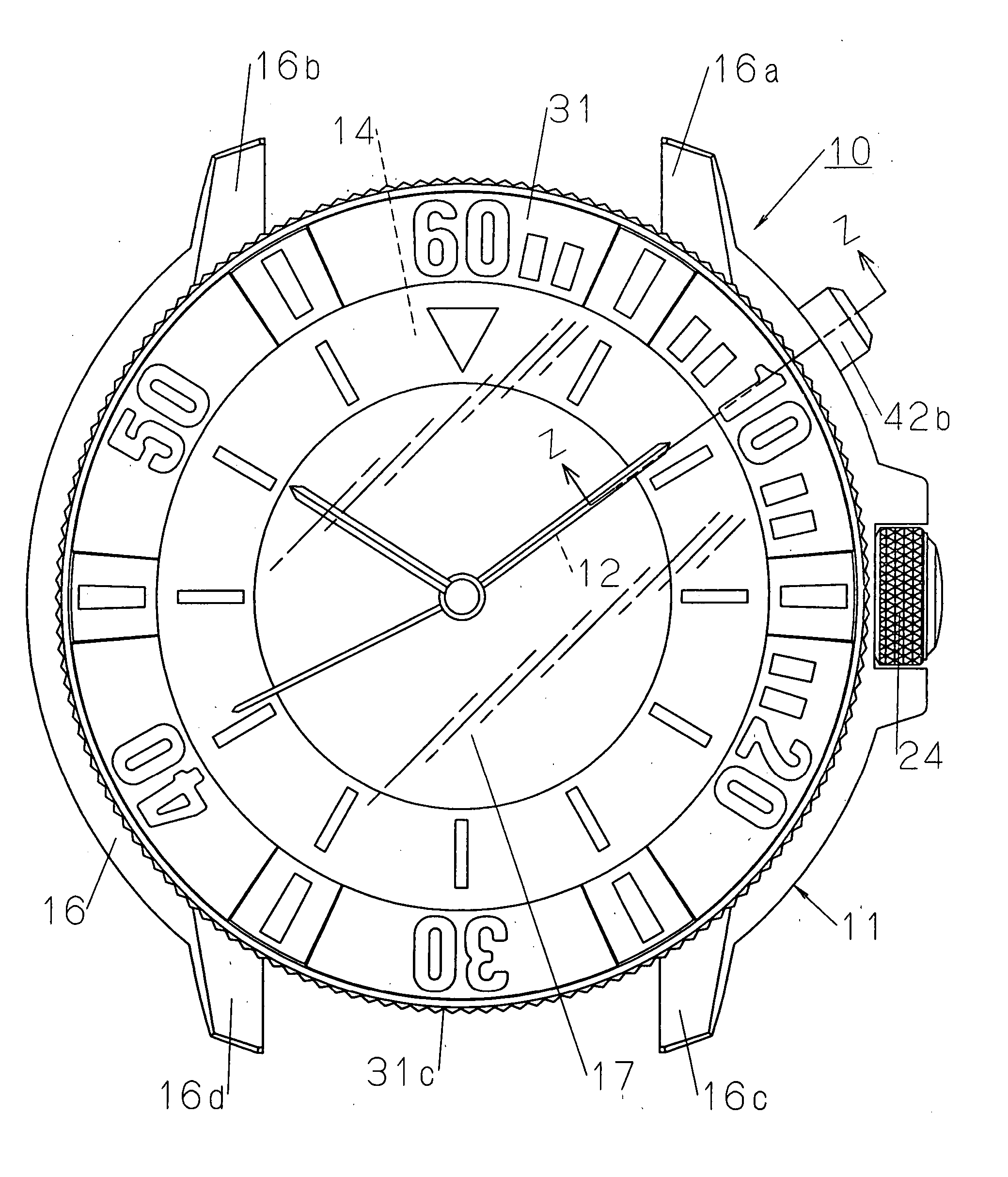
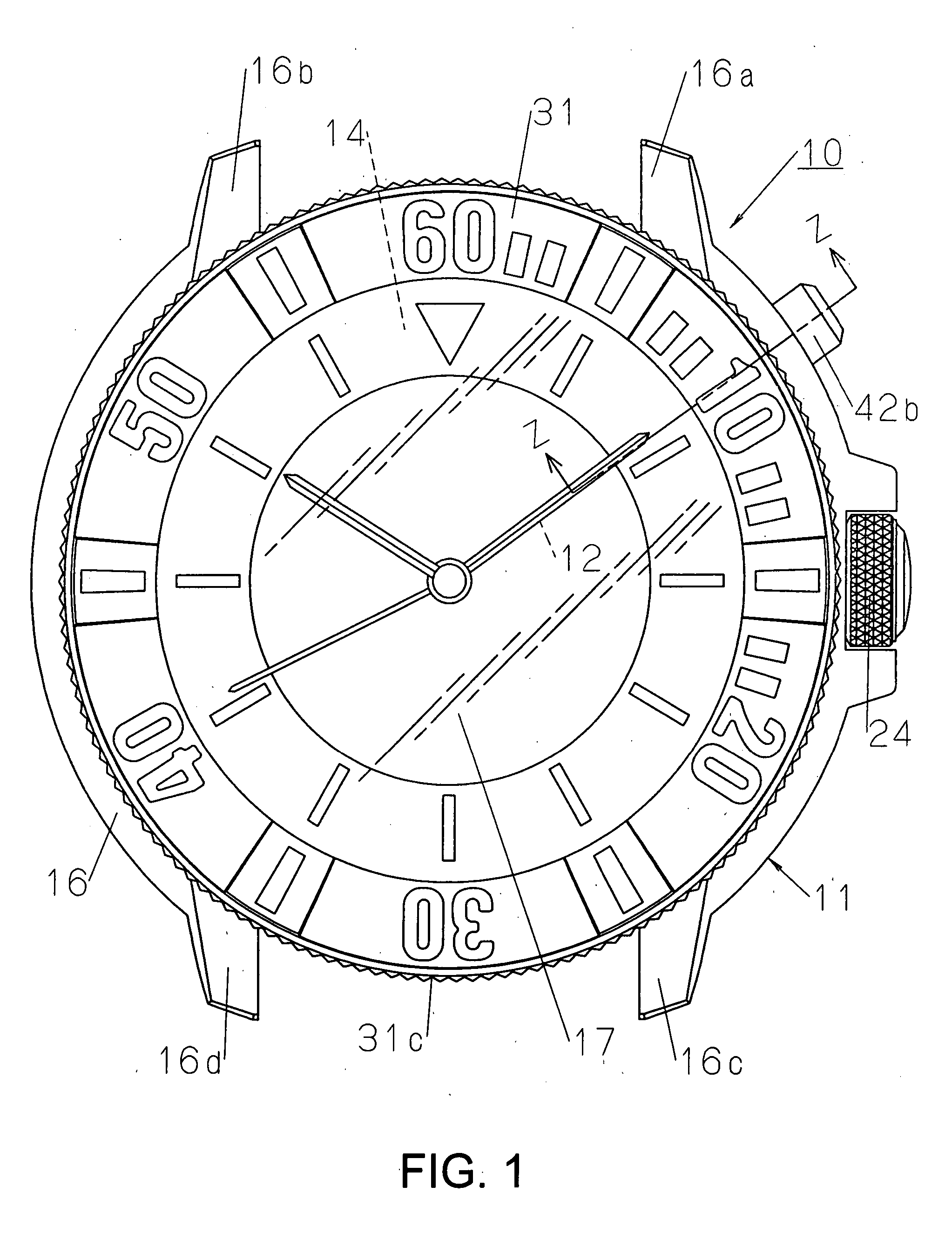
[0030] In FIGS. 1 to 4, symbol 10 denotes a portable timepiece or watch worn, for example, on the wrist for use. The watch exterior assembly 11 which the watch 10 includes holds e.g. a watch movement 13 (shown in FIGS. 3 and 4) for driving pointers 12, a dial plate 14 attached to the watch movement 13 and a frame member 15 (shown in FIGS. 3 and 4) for holding the watch movement 13 in the watch exterior assembly 11.

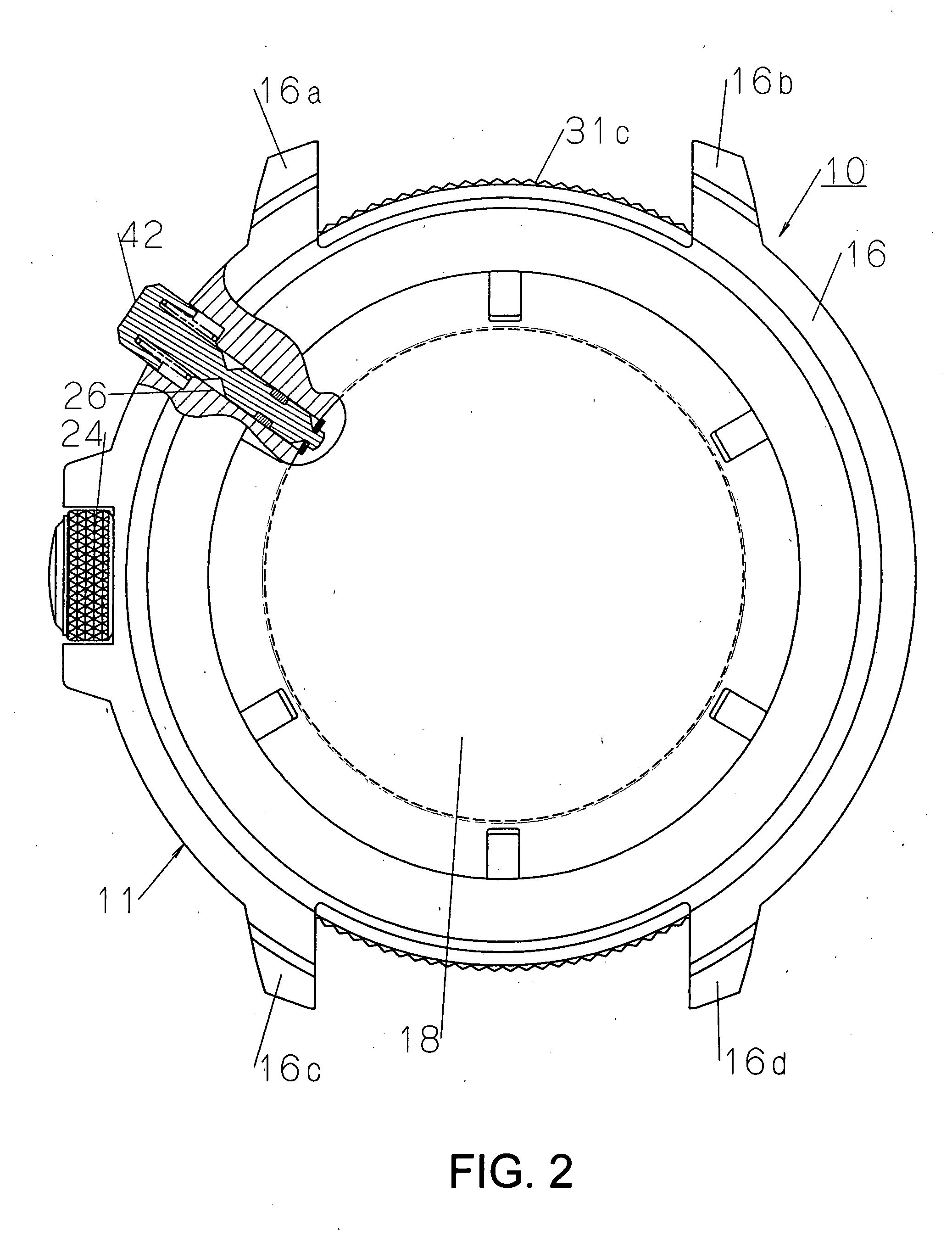
[0031] The watch exterior assembly 11 has a case band 16 preferably formed from a metal in an annular shape, a cover glass 17 attached in a liquid-tight way to one face of the case band 16 as viewed across its thickness (its front face) and aback cover 18 screwed removably to the other surface of the case band 16 as viewed across its thickness (its back face), as shown in FIGS. 1 to 4. The pointers 12 and the dial plate 14 are visible through the cover glass 17. In FIGS. 3 and 4, symbol 19 d...


PUM


Abstract

To provide a timepiece having a bezel which is easy to set in position, and which is not inadvertently rotatable after it has been set in position. A bezel is rotatably mounted on the bezel mounting portion of a case band. A click member is held vertically movably in the stepped hole of the case band and is urged toward the engaging portion of the bezel composed of a plurality of serrations. An operating member which has a depression having an oblique push-up surface and a closing surface contiguous to its push-up surface is held movably in a accommodating portion formed in the case band and crossing the lower end of the stepped hole at right angles thereto. The operating member is urged to its position in which its closing surface closes the lower end of the stepped hole. A stopper member capable of entering and leaving the depression along its push-up surface is positioned between the click member and the operating member. The member is movable to restrict the movement of the click member by the stopper member supported on its closing surface, while releasing the click member from such restriction and permitting its vertical movement by allowing the member to drop into the depression.

Description

BACKGROUND OF THE INVENTION [0001] 1. Field of the Invention [0002] The present invention is concerned with a portable timepiece, such as a wrist or pocket watch, and more particularly relates to a timepiece having a rotatable bezel. [0003] 2. Description of the Related Art [0004] It has hitherto been the case that a bezel mounted on a case band rotatably is held in a desired operating position by a structure producing a click feeling with its rotation. A click ball type and a leaf spring type are known as the structure for that purpose. [0005] The click ball type has a click groove formed in the rear surface of a bezel and having engaging teeth formed by a plurality of serrations lying in the direction of rotation of the bezel, a steel ball engageable with the engaging teeth and a coil spring holding the steel ball against the engaging teeth. According to this structure, the rotation of the bezel in either of clockwise and counterclockwise directions as desired causes the steel bal...

Claims


Application Information

Patent Timeline
Patent Type & Authority Applications(United States)
IPC IPC(8): G04B39/00
CPCG04B19/283G04B19/286
Inventor HIRANUMA, HARUKIITOH, KINSHUROH
Owner SEIKO INSTR INC
Why Eureka
Try Eureka