Noise reduction system and method

a noise reduction and noise technology, applied in the field of sound receiving devices and microphone units, can solve the problems of unfavorable sound transmission, undesirable noise signal that interferes with the use of the microphone, and the airflow incident upon the microphone may be so substantial, and achieve the effect of superior wind noise reduction

Active Publication Date: 2008-05-22
SONY CORP
View PDF4 Cites 34 Cited by
  • Summary
  • Abstract
  • Description
  • Claims
  • Application Information

AI Technical Summary

Benefits of technology

[0008]Implementations of the present in...

Problems solved by technology

In certain conditions, airflow incident upon the microphone may be so substantial as to be picked up by the microphone and produce an undesirable noise signal that interferes with the microphone's use.
During a phone call, for instance, audible airflow noise may make sound transmissions difficult to hear on the part of a listener.
Although omni-directional microphones are considered to be less sensitive to wind-noise from air blowing into microphone compared to directional microphones, wind-noise often remains problematic.
However, such electronic solutions requiring power consumption a...

Method used


Image

  • Noise reduction system and method
  • Noise reduction system and method
  • Noise reduction system and method

Examples


first embodiment

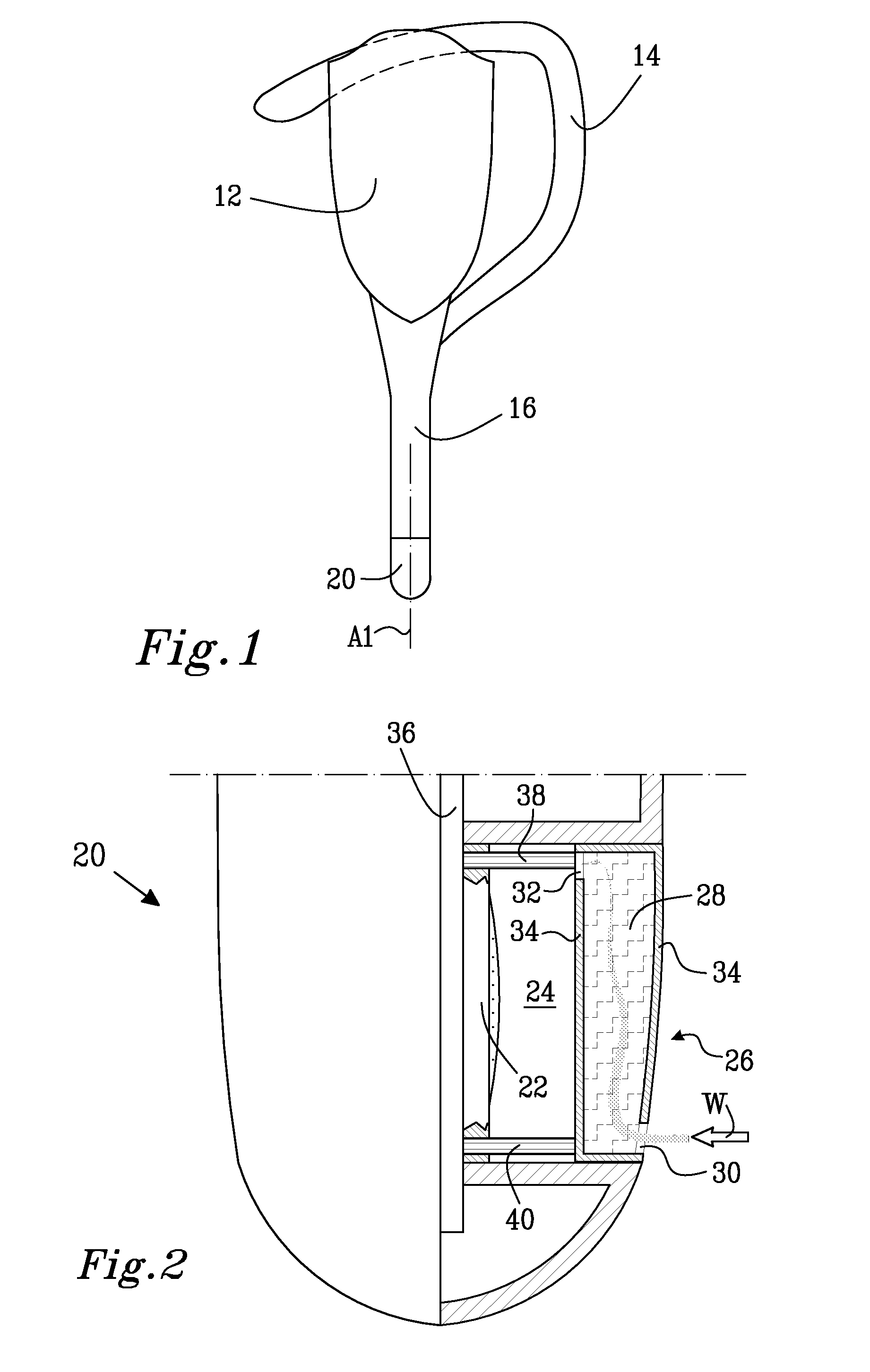
[0056]Barrier 26 may, in a first embodiment, be provided with an outer surface facing outwards to an area that is external of headset 10 and that is adapted in shape or conforms to, for example, the surrounding casing of second arm 16 so as to provide a substantially uniform exterior of headset 10. Barrier 26 may have an inner surface that is essentially parallel or coplanar with the outer surface and face chamber 24. Barrier 26 may have a first end provided at the first wall and a second end provided at the second wall. Barrier 26 may include an air passage channel 28 that may connect an exterior of headset 10 with chamber 24, i.e., be interposed between the exterior and chamber 24. For example, barrier 26 may have one or more openings that define an inlet 30 that is provided at the first end for interfacing the exterior and one ore more openings that define an outlet 32 provided at the second end for interfacing chamber 24.

[0057]Channel 28 may be substantially filled with a porous...

third embodiment

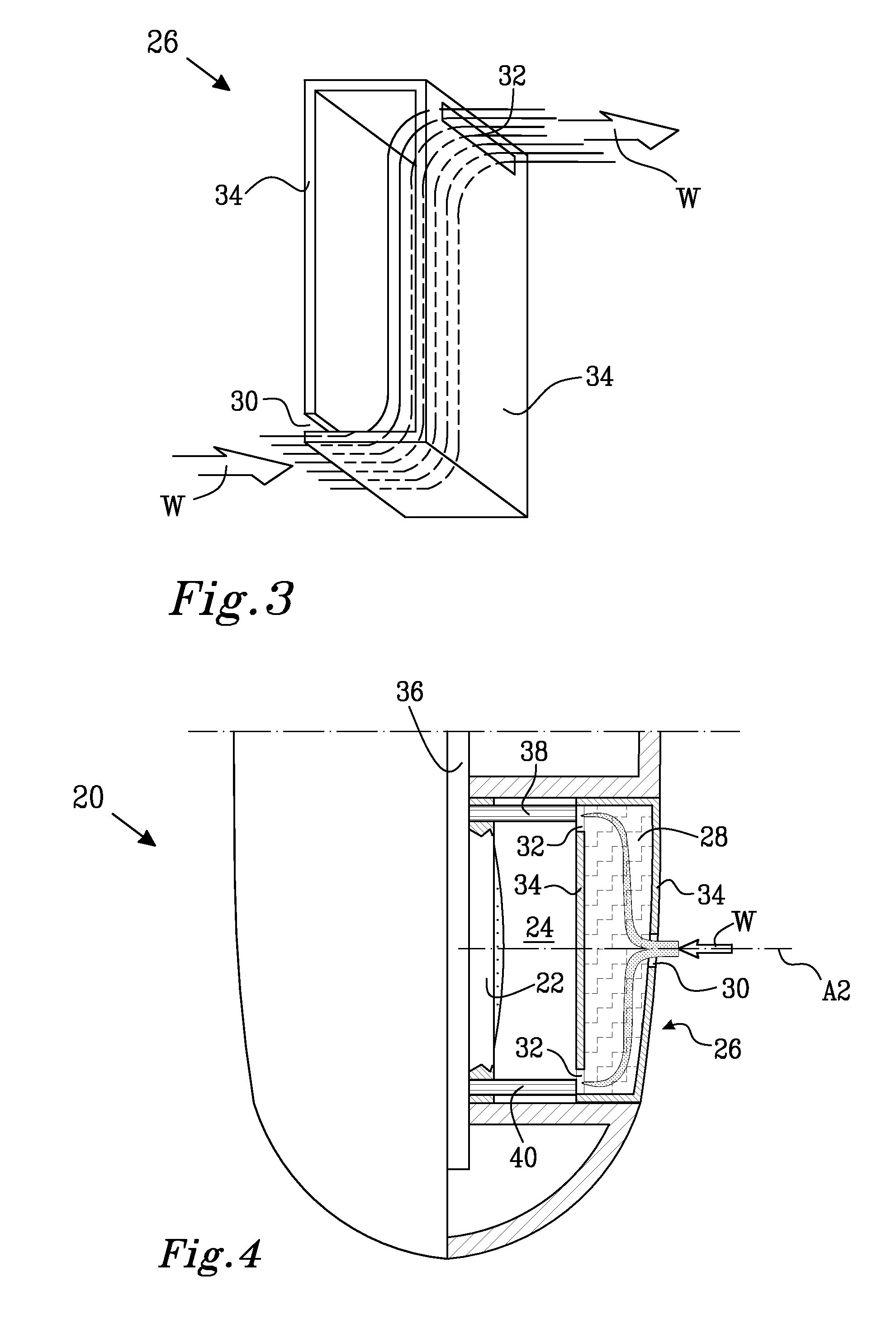
[0067]Channel 28 may be filled substantially as previously described with a porous, wind-reducing material and may include walls that are substantially airtight. Channel 28 may be provided along the inner and outer surfaces of barrier 26. Outlet 32 may be provided at the central top of the rounded end, while inlet 30 may be provided close to the bottom surface of chamber 24, so that sound waves and / or incidental air may travel a relatively extended distance inside channel 28 within the porous material. In the third embodiment, microphone 22 may be provided in a separate microphone chamber 46 that may connect with chamber 24 via, for example, a sound channel 44.

[0068]FIG. 6 schematically shows a perspective view of barrier 26 in microphone unit 20 according to the third embodiment. As can be seen, wind W can enter barrier 26 at the first end and exit barrier 26 at the second end.

[0069]The third embodiment may provide similar advantages to those of the second embodiment. Furthermore, ...

fourth embodiment

[0072]As shown in FIG. 7, the fourth embodiment may deviate in a number of ways from the exemplary arrangement shown in FIG. 4. For example, barrier 26 may be internally configured differently. Barrier 26 may be provided with one or more channels 28 traversing through barrier 26, for example, being defined by substantially airtight walls, and including porous wind reduction material and / or at least one turn or deflect. The number of curves or turns may vary, but for purposes of discussion, only one turn is shown. Inlets 30 associated with channels 28 may be provided at the outer surface of barrier 26 and substantially aligned with corresponding outlets 32 provided at the inner surface of barrier 26. Channels 28, for example, may be provided concentrically to axis A2. Other configurations of channels 28 vis-à-vis axis A2 and / or each other are possible.

[0073]The leading portion of channels 28 (e.g., before a first turn) that serves as an ingress to connect with inlet 30 may be provide...


PUM


Abstract

The present invention relates to a sound receiving device and a microphone unit for such a sound receiving device. In microphone unit there is provided a microphone, an air filled chamber and a wind noise barrier covering chamber for providing a wind shield and having at least one air passage channel connecting the exterior of the device with the air filled chamber and having an inlet facing the exterior of the device and an outlet facing the air filled chamber. The air passage channel comprises at least one turn for reducing the influence of the wind on microphone. The invention provides enhanced wind noise reduction.

Description

TECHNICAL FIELD OF THE INVENTION[0001]The present invention generally relates to the field of receiving of sound, using microphones and, more particularly to a sound receiving device and a microphone unit for such a sound receiving device.BACKGROUND ART[0002]Microphones used for portable electronic devices may be “directional” or “omni-directional.” Such devices (e.g., cellular telephones) may, at times, be used in circumstances in which the microphone is subject to transient (e.g., “popping” of a spoken “p” phoneme) or sustained (e.g., wind) airflow disturbance. In certain conditions, airflow incident upon the microphone may be so substantial as to be picked up by the microphone and produce an undesirable noise signal that interferes with the microphone's use. During a phone call, for instance, audible airflow noise may make sound transmissions difficult to hear on the part of a listener.[0003]Typically, several types of omni-directional microphones have been used in portable elect...

Claims


Application Information

Patent Timeline
IPC IPC(8): H04R9/08
CPCH04R2410/07H04R1/086
Inventor DE POOTER, PIETERSAMPIMON, GERRIT JOHANNES WILLEMSCHREUDER, JOHANNES LUCASSTUBENITSKY, RUDY
Owner SONY CORP
Why Eureka
Try Eureka