Roof parapet system

a roof parapet and parapet technology, applied in the field of roof parapet systems, can solve the problems cost billions of dollars annually around the world, and routinely occur roof covering failures, etc., and achieve the effects of reducing the risk of roof covering failur

Active Publication Date: 2012-04-12
ARCH GARTH
View PDF67 Cites 0 Cited by
  • Summary
  • Abstract
  • Description
  • Claims
  • Application Information

AI Technical Summary

Benefits of technology

[0006]The present invention advantageously provides cost-effective structures and methods that mitigate the uplift effect caused by vortices created due to incident high winds and that can further readily integrate with existing structures without the need for significant architectural or structural modifications. For example, a roof parapet system is provided that generally includes a parapet body or panel positionable in or about a drain channel or gutter coupled to an edge or fascia of a roof. The parapet body defines a plu

Problems solved by technology

Property losses due to windstorms cost billions of dollars annually around the world.
Roof covering failures, in particular, routinely occur during the increased wind velocities experienced during hurricanes and other violent storms.
High winds result in increased suction forces on a roof that can severely

Method used


Image

  • Roof parapet system
  • Roof parapet system
  • Roof parapet system

Examples


Embodiment Construction

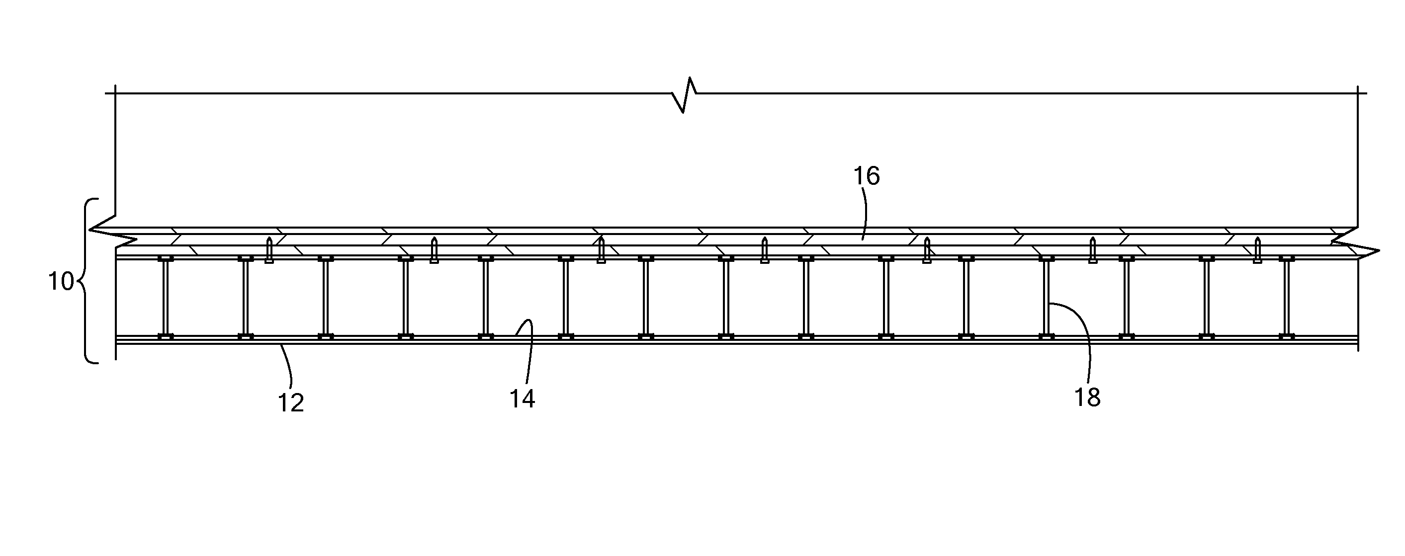
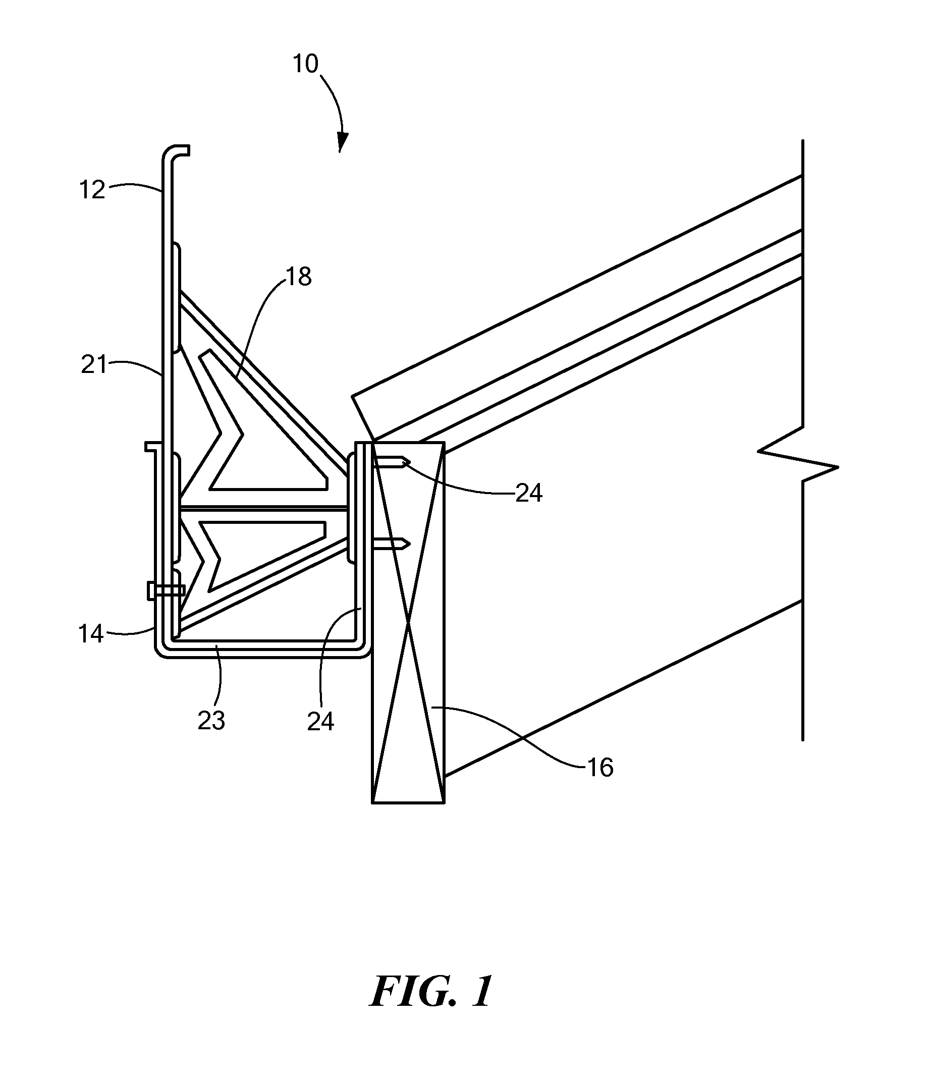
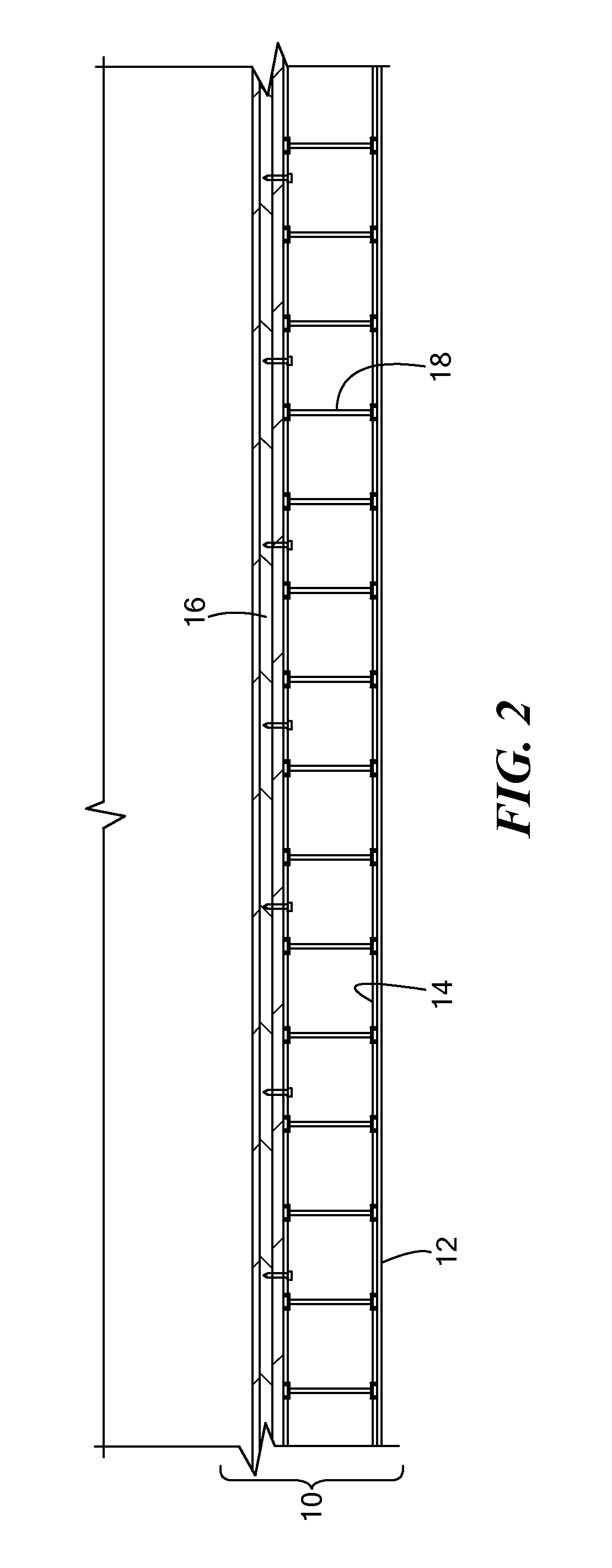
[0016]The present invention advantageously provides cost-effective structures and methods that mitigate the uplift effect caused by vortices created due to incident high winds and that can further readily integrate with existing structures without the need for significant architectural or structural modifications. In particular and now referring to the figures where like reference designators refer to like components, there is shown a suction force or wind force mitigating, roof parapet system generally designated as 10. The roof parapet system 10 generally includes a parapet body or panel 12 positionable in or about a drain channel or gutter 14 coupled to an edge of a roof 16. The parapet body or panel may also be directly attached to a fascia or outer panel of a roof 16 or portion of the structure itself to extend above the roofline. The system 10 may further include one or more structural support members 18 engageable with the parapet panel 12 and / or the drain channel 14 to aid i...


PUM


Abstract

A wind mitigation system is disclosed, including a panel engageable with a drain channel of a roof, the panel dimensioned to extend above a top edge defined by the drain channel, wherein the panel defines a plurality of openings; and a structural support member coupled to the panel, the structural support member providing increased rigidity of the panel.

Description

CROSS-REFERENCE TO RELATED APPLICATION[0001]This application is related to and claims priority to U.S. Provisional Application Ser. No. 61 / 391,721, filed Oct. 11, 2010, entitled ROOF PARAPET SYSTEM , the entirety of which is incorporated herein by reference.STATEMENT REGARDING FEDERALLY SPONSORED RESEARCH OR DEVELOPMENT[0002]n / aFIELD OF THE INVENTION[0003]The present invention relates to systems and methods of use thereof for reducing roof susceptibility to undesired suction forces occurring during high winds and turbulent weather.BACKGROUND OF THE INVENTION[0004]Property losses due to windstorms cost billions of dollars annually around the world. Roof covering failures, in particular, routinely occur during the increased wind velocities experienced during hurricanes and other violent storms. High winds result in increased suction forces on a roof that can severely damage or completely destroy the roof. Of course, once the roof of a structure is compromised, or even worse, completel...

Claims


Application Information

Patent Timeline
IPC IPC(8): E04H9/14E04B1/92E04D13/00
CPCE04D13/00
Inventor ARCH, GARTH
Owner ARCH GARTH
Why Eureka
Try Eureka