Method for Producing a Reversible Solid Oxide Fuel Cell

a solid oxide fuel cell and oxidation method technology, applied in the direction of cell components, final product manufacturing, sustainable manufacturing/processing, etc., can solve the problems of oxidation of anodes, negative impact on the overall cell performance, and material use challenges

Inactive Publication Date: 2008-05-22
DANMARKS TEKNISKE UNIV
View PDF59 Cites 33 Cited by
  • Summary
  • Abstract
  • Description
  • Claims
  • Application Information

AI Technical Summary

Problems solved by technology

Solid oxide fuel cells (SOFCs) operate at high temperatures which are generally in the range of about 750° C. to about 1000° C. These high temperatures are challenging to the materials employed, and are of particular concern with regard to the stability of the anode structures.
However, during the sintering of the half cell, undesired reactions between the metal support and anode materials may occur, resulting in a negative impact on the overall cell performance.
Moreover, in the prevalent anode supported design, oxidation of the anode is known to be detrimental for the cell performance.
The above mentioned method constitutes some limitations on the anode material to be used.
While such a solid oxide fuel cell is relatively cheap and avoids the use of brittle seals, the SOFC it is not sufficiently robust.
The teaching of US 2002 / 0048699 furthermore does not overcome the above mentioned problems related to the manufacturing process of the SOFC.

Method used


Image

  • Method for Producing a Reversible Solid Oxide Fuel Cell
  • Method for Producing a Reversible Solid Oxide Fuel Cell

Examples


example 1

Preparation of a Reversible SOFC with Porous Cathode Impregnation Layer

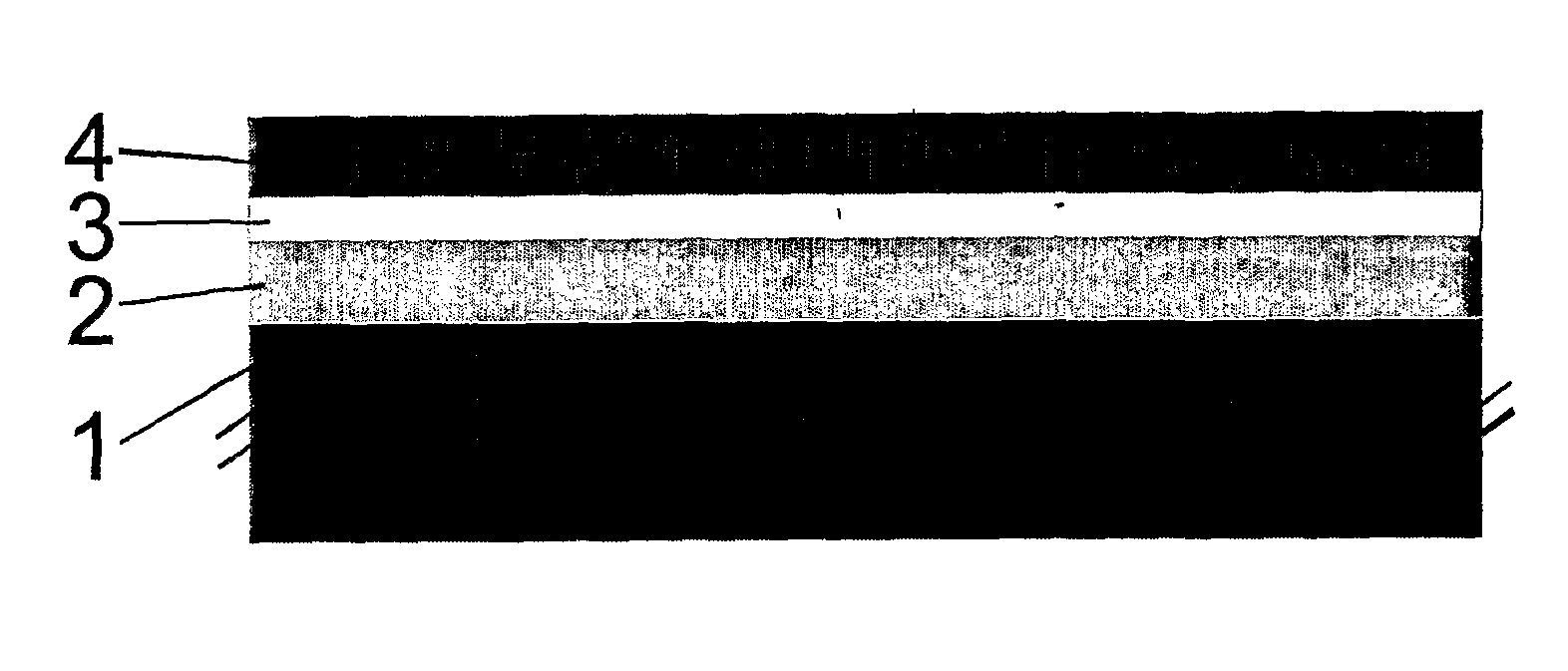
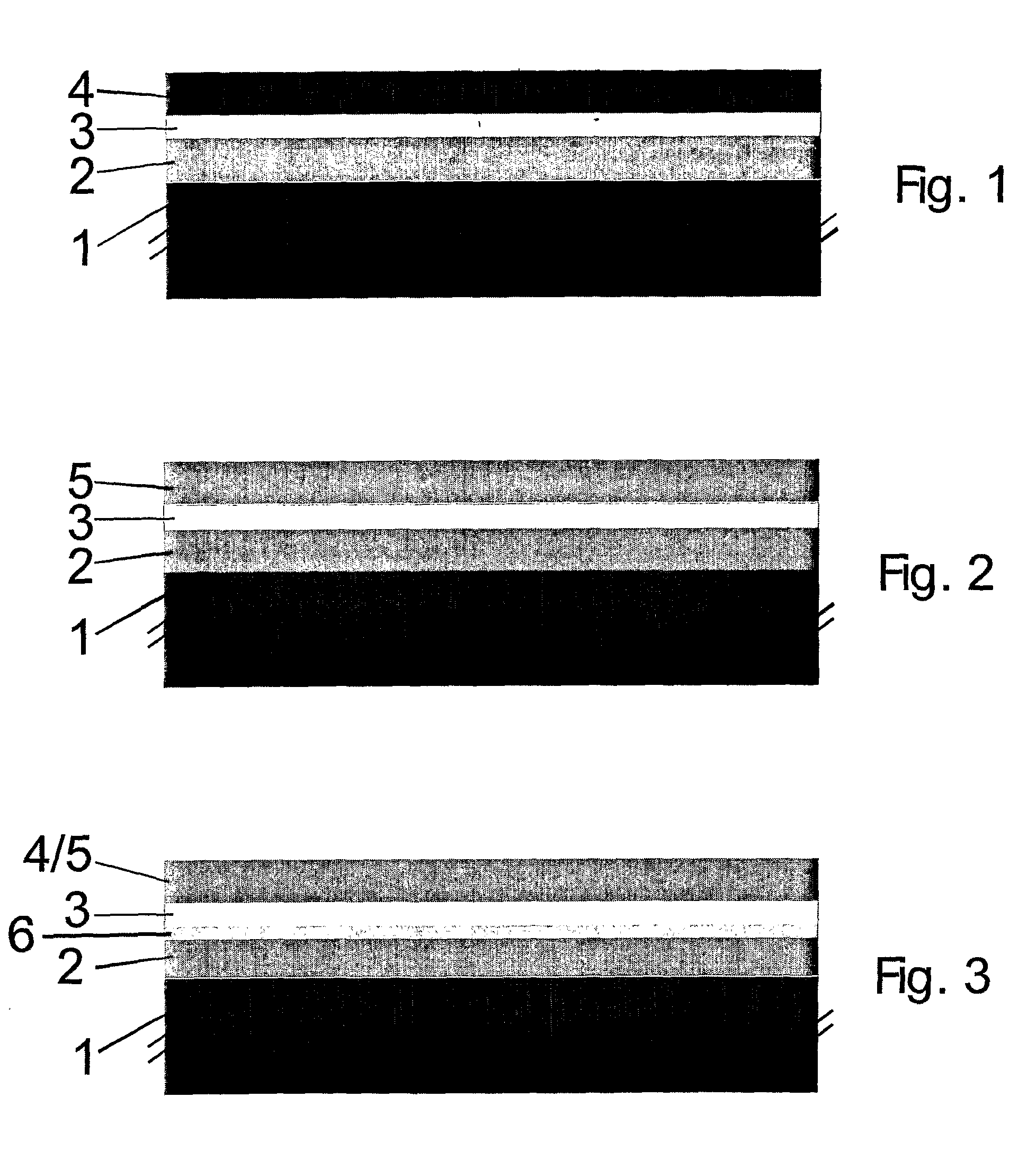
[0084]A metallic support layer was tape-cast from a powder suspension comprising a Fe22Cr alloy, followed by a drying step. The support layer had a thickness of 300 μm. Thereon, a porous layer comprising Zr0.78Sc0.20Y0.02O2-δ for later impregnation of the cathode was formed by spray painting. The layer had a thickness of 50 μm and a porosity of about 40% with an average pore size of about 1-3 μm. Then, an electrolyte layer comprising Zr0.78Sc0.20Y0.02O2-δ was formed thereon, also by spray painting. The electrolyte layer was formed from doped zirconia and had a thickness of about 10 μm. The obtained multi-layer structure was dried, followed by sintering under reducing conditions at about 1300° C.

[0085]After sintering a nitrate solution of (Gd0.1Ce0.9)O2-δ and (La0.6Sr0.4)0.98(Cu0.2Fe0.8)O3-δ was impregnated in to the cathode precursor layer by vacuum infiltration. The nitrates were subsequently decomposed at 500° ...

example 2

[0087]A metallic support layer was tape-cast from a powder suspension comprising a FeCrMn0.01 alloy, followed by a drying step. The support layer had a thickness of 400 μm.

[0088]After drying of the support layer, a layer for later electrode impregnation (layer 2, 50 micrometer) was deposited by screen-printing an ink comprising a 1:1 volume mixture of Zr0.78Sc0.20Y0.02Zr2-δ and a Fe24CrMn0.01 The layer had a thickness of 50 μm. Finally an electrolyte layer comprising Zr0.78Sc0.20Y0.02O2-δ was deposited by spray painting.

[0089]The multilayer structure was sintered and the cathode impregnated as described in Example 1.

[0090]After sintering a redox stable anode was deposited by spray painting a suspension of NiO—Zr0.78Sc0.20Y0.02Zr2-δ—TiO2. (52:43:5 weight %, respectively), followed by an additional sintering step at about 1000° C. in air. During sintering of the anode, NiTi2O4 was formed in the anode structure. The redox stable microstructure was created during the initial reduction o...

example 3

[0091]Same method as in Example 2, but with the composition for the redox stable anode comprising pre-reacted NiTiO3 before processing.


PUM

PropertyMeasurementUnit
temperaturesaaaaaaaaaa
thicknessaaaaaaaaaa
thicknessaaaaaaaaaa

Abstract

The present invention provides a method for producing a reversible solid oxide fuel cell, comprising the steps of: —providing a metallic support layer; —forming a cathode precursor layer on the metallic support layer; —forming an electrolyte layer on the cathode precursor layer; —sintering the obtained multilayer structure; —impregnating the cathode precursor layer so as to form a cathode layer; and —forming an anode layer on top of the electrolyte layer. Furthermore, a reversible SOFC is provided which is obtainable by said method. The method advantageously allows for a greater choice of anode materials, resulting in more freedom in cell design, depending on the desired application.

Description

FIELD OF THE INVENTION[0001]The present invention relates to a method for producing a reversible solid oxide fuel cell (SOFC / SOEC) comprising a metallic support, and to a reversible solid oxide fuel cell obtainable by said method.BACKGROUND ART[0002]Solid oxide fuel cells (SOFCs) operate at high temperatures which are generally in the range of about 750° C. to about 1000° C. These high temperatures are challenging to the materials employed, and are of particular concern with regard to the stability of the anode structures. For fuel oxidation, the so far preferred anode material comprises metallic nickel. Nickel is also preferred for reformed hydrocarbon fuel since it is a good catalyst for hydrocarbon reformation.[0003]Manufacture processes suggested in the prior art include the provision of a support, the formation of an anode layer thereon, followed by the application of an electrolyte layer. The so formed half cell is dried and afterwards sintered, often in a reducing atmosphere....

Claims


Application Information

Patent Timeline
Patent Type & Authority Applications(United States)
IPC IPC(8): B05D5/12H01M4/88H01M8/12
CPCH01M4/8885H01M4/9025H01M4/905H01M8/023H01M8/0232H01M8/0243Y10T29/49115H01M8/126H01M8/184H01M2008/1293Y02E60/525Y02E60/528H01M8/1253Y02E60/50Y02P70/50
Inventor LARSEN, PETER HALVOR
Owner DANMARKS TEKNISKE UNIV
Why Eureka
Try Eureka