Apparatus for dental oct imaging

a technology for oct imaging and dental apparatus, applied in the field of dental oct imaging apparatus, can solve the problems of permanent tooth damage and even tooth loss, exposure to x-ray radiation, risk of damage to weakened teeth, and spreading infection by tactile methods

Inactive Publication Date: 2008-05-22
CARESTREAM HEALTH INC
View PDF22 Cites 146 Cited by
  • Summary
  • Abstract
  • Description
  • Claims
  • Application Information

AI Technical Summary

Benefits of technology

[0037]The method of the present invention is advantaged over earlier methods for OCT imaging in that it combines the

Problems solved by technology

If not properly and promptly treated, caries can lead to permanent tooth damage and even to loss of teeth.
There are also hazards associated with conventional detection techniques, including the risk of damaging weakened teeth and spreading infection with tactile methods as well as exposure to x-ray radiation.
By the time caries is evident under visual and tactile examination, the disease is generally in an advanced stage, requiring a filling and, if not timely treated, possibly leading to tooth loss.
One recognized drawback with existing techniques that employ fluorescence imaging relates to image contrast.
The image provided by fluorescence generation techniques such as QLF can be difficult to assess due to relatively poor contrast between healthy and infected areas.
As noted in the '2356 Stookey et al. disclosure, spectral and intensity changes for incipient caries can be very slight, making it difficult to differentiate non-diseased tooth surface irregularities from incipient caries.
In such cases, detection accuracy using fluorescence techniques may not show marked improvement over conventional methods.
Because of this shortcoming, the use of fluorescence effects appears to have some practical limits that prevent accurate diagnosis of incipient caries.
As a result, a caries condition may continue undetected until it is more serious, requiring a filling, for example.
As noted earlier, conventional techniques gener

Method used


Image

  • Apparatus for dental oct imaging
  • Apparatus for dental oct imaging
  • Apparatus for dental oct imaging

Examples


Embodiment Construction

[0064]The present description is directed in particular to elements forming part of, or cooperating more directly with, apparatus in accordance with the invention. It is to be understood that elements not specifically shown or described may take various forms well known to those skilled in the art.

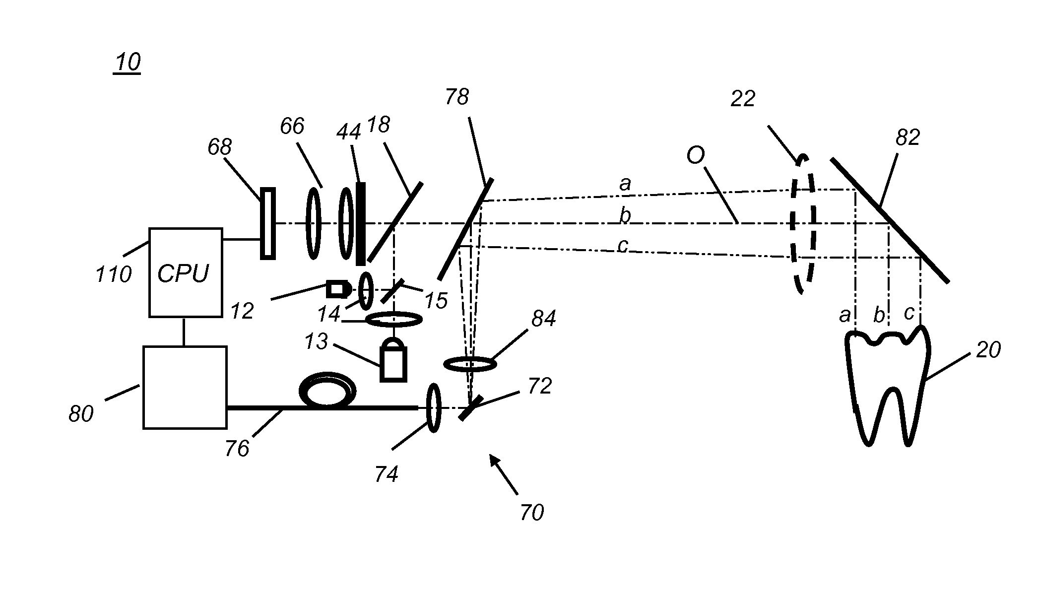
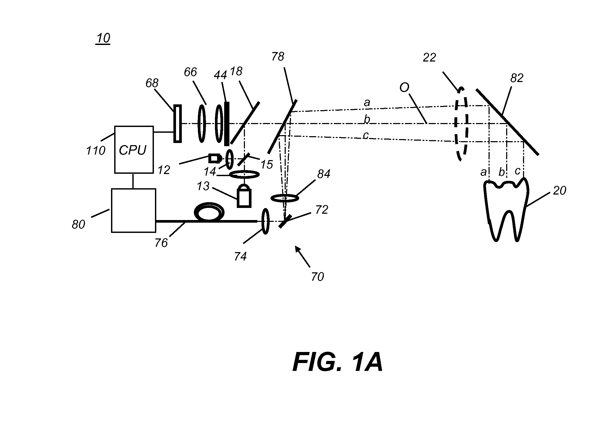
[0065]The present invention combines area imaging capabilities for identifying a region or regions of interest on the tooth surface with OCT imaging capabilities for obtaining detailed OCT scan data over a specified portion of the tooth corresponding to a portion of the region of interest. A region of interest is defined as a region of the tooth which has features indicative of potential caries sites or exhibits other defects which would warrant further investigation by OCT imaging. In order to understand the nature and scope of the present invention, it is instructive to first understand its area imaging capabilities. OCT capabilities are then described subsequently. A variety of area ima...


PUM


Abstract

An apparatus (10) for obtaining an image of a tooth (20) includes an image sensor and a white light source (12) providing broadband polychromatic light and an ultraviolet light source providing narrow-band light. A combiner (15) directs broadband polychromatic light and narrow band light along a common illumination path to illuminate the tooth. A polarization beamsplitter (18) directs polarized light from the illumination path along an optical axis (216). An optical coherence tomography (OCT) imaging apparatus (70) splits the low coherence light into a sample path and a reference path and a dichroic element (78) directs the polarized illumination and the sample path low coherence light along the optical axis. An image processor (100) identifies a region of interest according to either a white light image (124), a fluorescent light image (120), or both and the OCT imaging apparatus obtains an OCT image over the region of interest.

Description

CROSS REFERENCE TO RELATED APPLICATIONS[0001]Reference is made to commonly-assigned copending U.S. application Ser. No. 11 / 262,869, filed Oct. 31, 2005, entitled METHOD FOR DETECTION OF CARIES, by Wong et al.; U.S. application Ser. No. 11 / 408,360, filed Apr. 21, 2006, entitled OPTICAL DETECTION OF DENTAL CARIES by Wong et al.; U.S. patent application Ser. No. 11 / 530,987, filed Sep. 12, 2006, entitled APPARATUS FOR CARIES DETECTION, by Liang et al.; and U.S. patent application Ser. No. 11 / 530,913, filed Sep. 12, 2006, entitled LOW COHERENCE DENTAL OCT IMAGING, by Liang et al., the disclosures of which are incorporated herein.FIELD OF THE INVENTION[0002]This invention generally relates to methods and apparatus for dental imaging and more particularly relates to an apparatus for caries detection using visible light, fluorescent light, and low coherence OCT imaging.BACKGROUND OF THE INVENTION[0003]In spite of improvements in detection, treatment, and prevention techniques, dental caries...

Claims


Application Information

Patent Timeline
IPC IPC(8): A61C3/00
CPCA61B5/0088A61B5/0066
Inventor LIANG, RONGGUANGMARCUS, MICHAEL A.PATTON, DAVID L.VOCI, LAURIE L.WONG, VICTOR C.MCLAUGHLIN, PAUL O.BRIDGES, MARK E.
Owner CARESTREAM HEALTH INC
Why Eureka
Try Eureka