
Endoscope And Supportive Member For Bending Operation Of The Same

a technology of supporting member and endoscope, which is applied in the field of endoscope and supporting member for bending operation of endoscope, can solve the problems of not easy to adjust the direction of the bendable portion of the endoscope in four directions, and not easy to manipulate two bending operation knobs simultaneously in order

Active Publication Date: 2008-05-22
OLYMPUS CORP
View PDF8 Cites 15 Cited by
  • Summary
  • Abstract
  • Description
  • Claims
  • Application Information

AI Technical Summary

Benefits of technology

The present invention relates to an endoscope with a bendable portion. The endoscope includes an operation portion with two bending operation knobs. The first bending operation knob has plural depressions and plural first protrusions, which bends the bendable portion in a first direction when rotated. The second bending operation knob has plural depressions and plural second protrusions, which bends the bendable portion in a second direction when rotated. The second protrusions have a longer length than the first protrusions and at least one of them has a depression near the center of rotation of the first protrusions. The technical effect of this invention is to provide an improved endoscope with a more efficient and effective bending mechanism for the bendable portion.

Problems solved by technology

For medical doctors with small hands, it is not easy to adjust the direction of the bendable portion of the endoscope in four directions, in other words, it is not easy to manipulate two bending operation knobs simultaneously in order to bend the bendable portion in rightward / leftward or upward / downward.

Method used


Image

  • Endoscope And Supportive Member For Bending Operation Of The Same
  • Endoscope And Supportive Member For Bending Operation Of The Same
  • Endoscope And Supportive Member For Bending Operation Of The Same

Examples


Embodiment Construction

[0021]Exemplary embodiments of the present invention will be described below with reference to the accompanying drawings. It should be noted that the present invention is not limited to the embodiments described below.

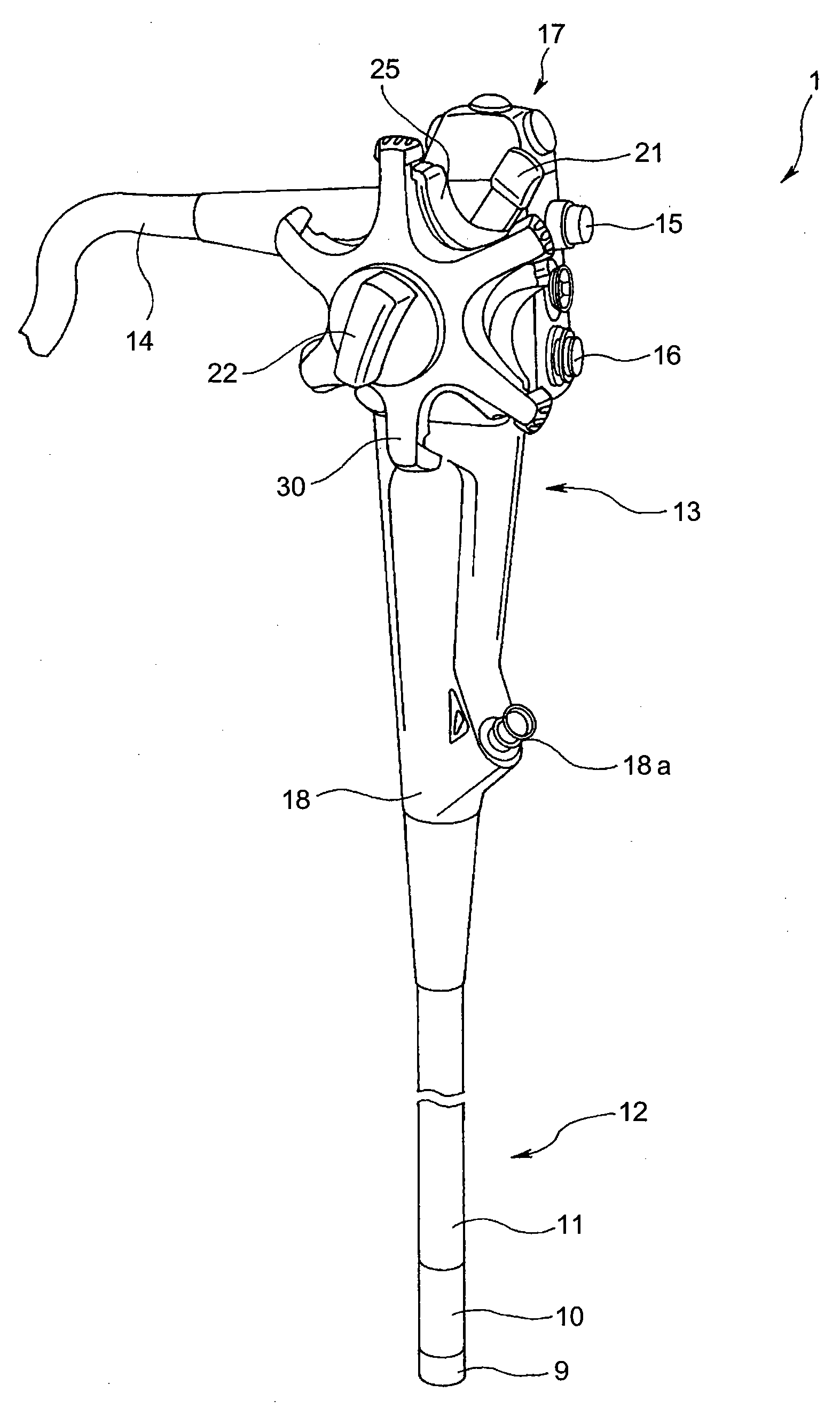
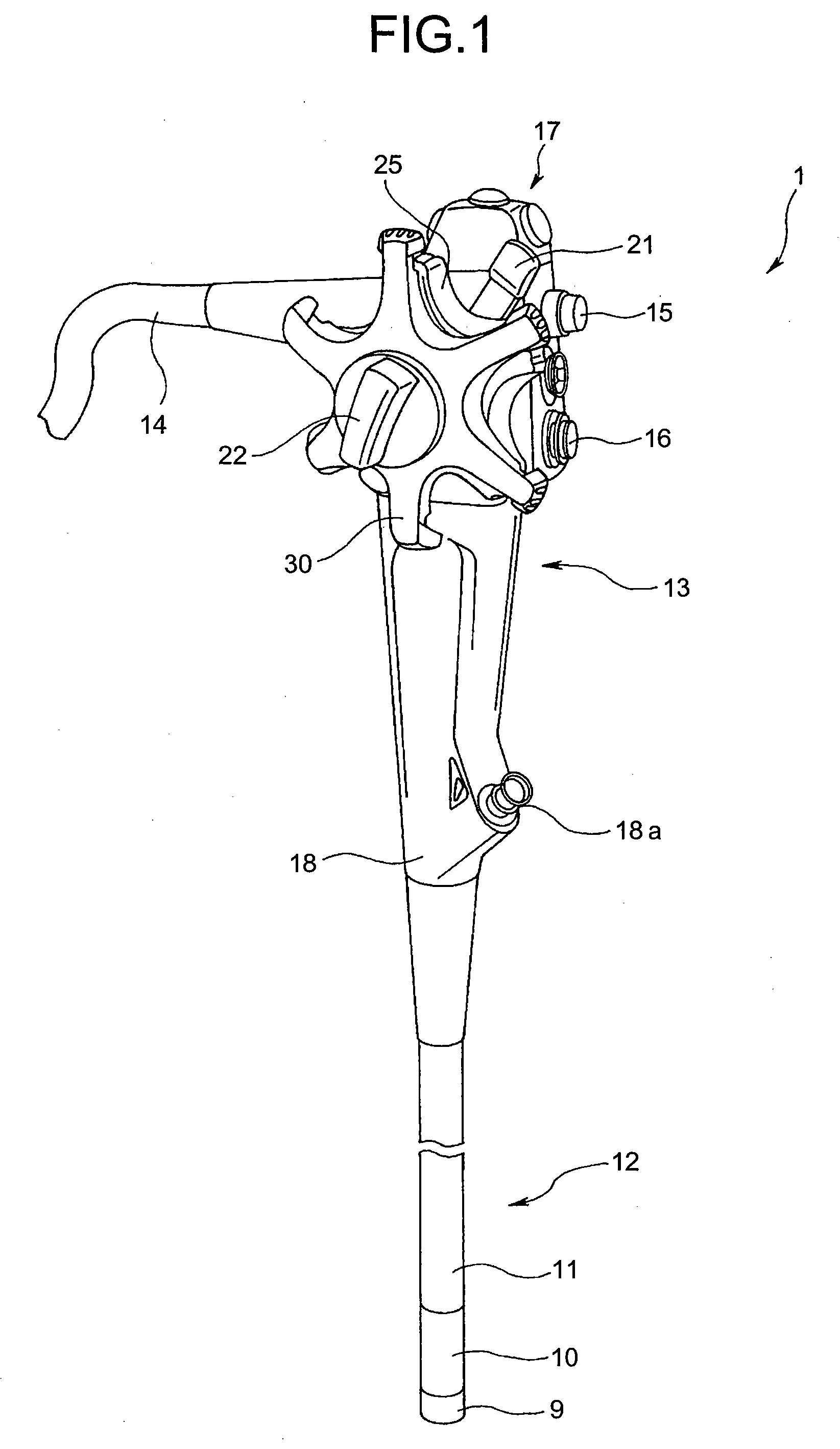
[0022]FIGS. 1 to 4 show a structure of an endoscope according to a first embodiment of the present invention. FIG. 1 is a schematic view of a schematic structure of the endoscope of the present invention. As shown in FIG. 1, an endoscope 1 of the first embodiment mainly includes an operation portion 13 in which various kinds of operation levers are provided, an elongated flexible insertion portion 12 which extends from the operation portion 13, and a universal cord 14 which extends from a side of the operation portion 13 and in which a light guide, a signal line, and the like are inserted. The endoscope 1 is detachably connected to a light source (not shown) as an external device, a processor (not shown) as a signal processing device, and the like, through a connector ...


PUM


Abstract

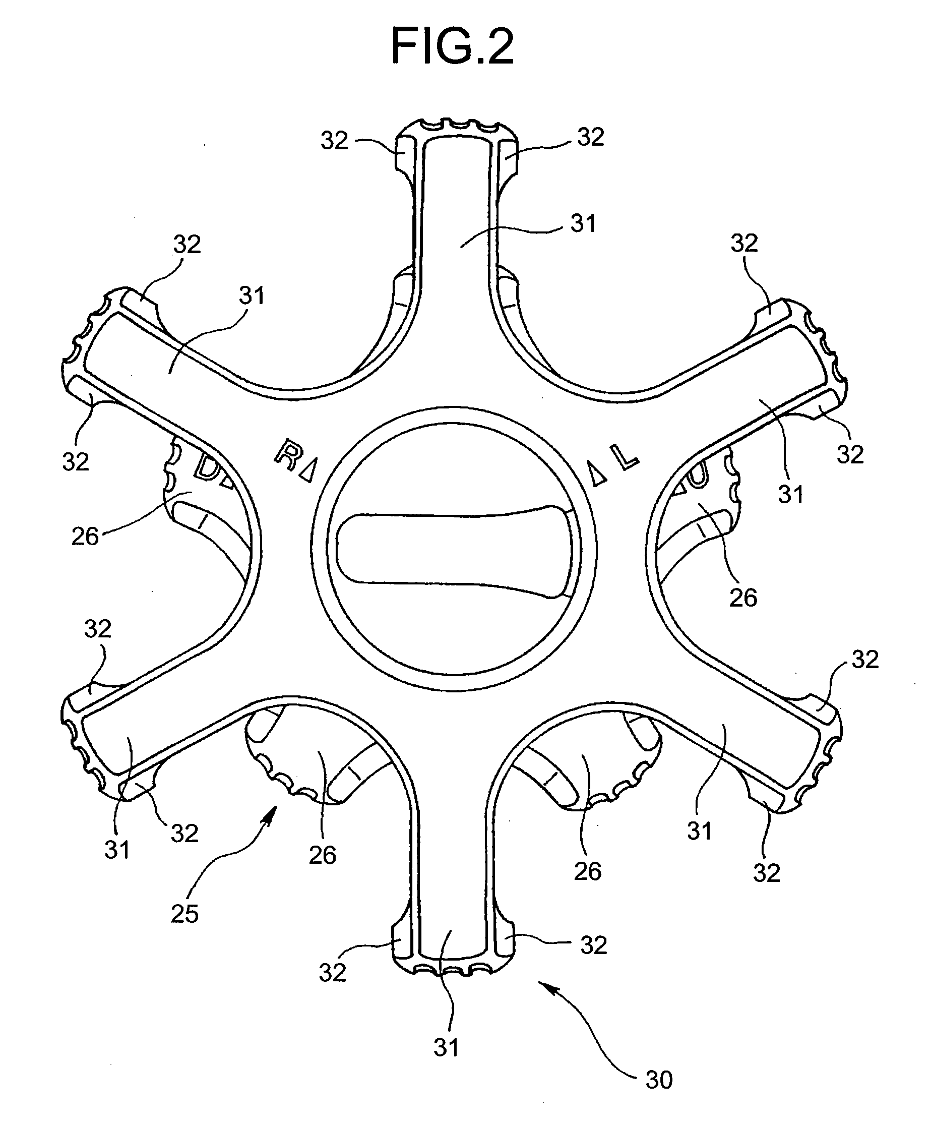
An endoscope includes an insertion portion having a bendable portion; an operation portion from which the insertion portion extends; a first bending operation knob arranged on a surface of the operation portion and including depressions and first protrusions, to bend the bendable portion in a first direction when rotated; and a second bending operation knob arranged over the first bending operation knob and including depressions and second protrusions, to bend the bendable portion in a second direction when rotated. A length of the second protrusion from a center of rotation to a tip portion is longer than a length of the first protrusion from the center of rotation to tip portions of the first protrusions, and the second protrusion has a depression near a projection of a circular orbit of rotation of each tip portion of the first protrusions onto a surface facing the first bending operation knob.

Description

CROSS-REFERENCE TO RELATED APPLICATIONS[0001]This application is a continuation of PCT international application Ser. No. PCT / JP2005 / 011126 filed Jun. 17, 2005 which designates the United States, incorporated herein by reference, and which claims the benefit of priority from Japanese Patent Application No. 2004-180190, filed Jun. 17, 2004, incorporated herein by reference.BACKGROUND OF THE INVENTION[0002]1. Field of the Invention[0003]The present invention relates to an endoscope and a supportive member for bending operation of the endoscope, and more particularly to an endoscope in which a bending operation knob is provided and a supportive member for bending operation of the endoscope.[0004]2. Description of the Related Art[0005]Conventionally, endoscopes are widely utilized for observations and various kinds of treatments of examined regions inside body cavities and the like. The endoscope has an elongated insertion portion which can be inserted inside the body cavities.[0006]The...

Claims


Application Information

Patent Timeline
Patent Type & Authority Applications(United States)
IPC IPC(8): A61B1/008A61B1/00A61B1/005
CPCA61B1/0052
Inventor MORIYAMA, HIROKI
Owner OLYMPUS CORP
Learn More