Short stem femoral prosthesis

a femoral prosthesis and short stem technology, applied in the field of short stem prosthesis, can solve problems such as endangering the stability of the stem, and achieve the effects of increasing the potential for boney in-growth, maximum rotational stability, and large surface area

Inactive Publication Date: 2008-05-22
BENOIST GIRARD & CIE
View PDF5 Cites 10 Cited by
  • Summary
  • Abstract
  • Description
  • Claims
  • Application Information

AI Technical Summary

Benefits of technology

[0007]It is believed that a stem of this shape has the advantage to respect and spare the tractive trabecular system in the supero-lateral part of the femur. This portion is usually referred to as the principle tensile group and is usually not spared, even with the use of conservative standard long stem hip implants.
[0008]The gutter or u-shape allows the introduction of the stem with the minimal removal of bo

Problems solved by technology

Stress shielding can be expected and the consequent reabso

Method used


Image

  • Short stem femoral prosthesis
  • Short stem femoral prosthesis
  • Short stem femoral prosthesis

Examples


Embodiment Construction

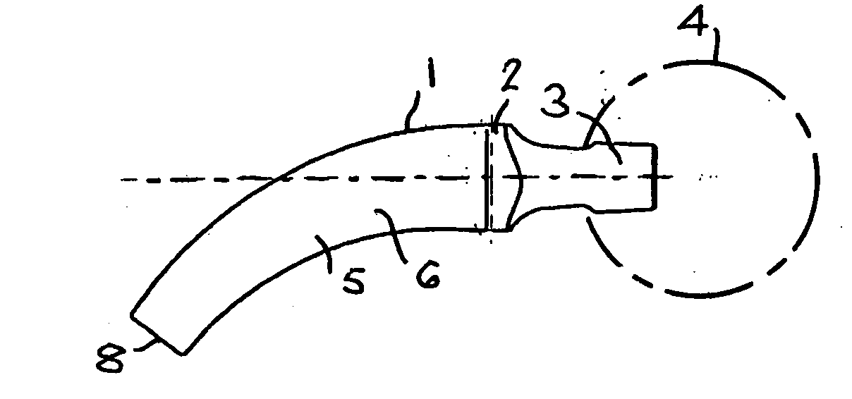
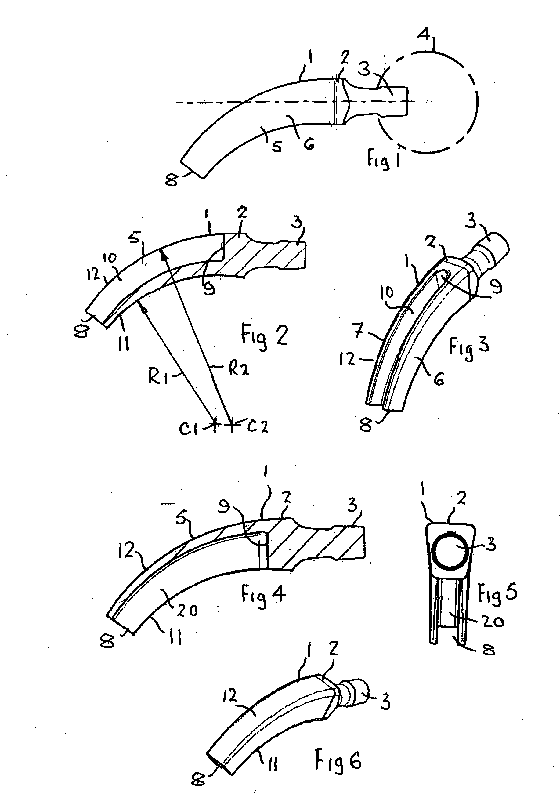
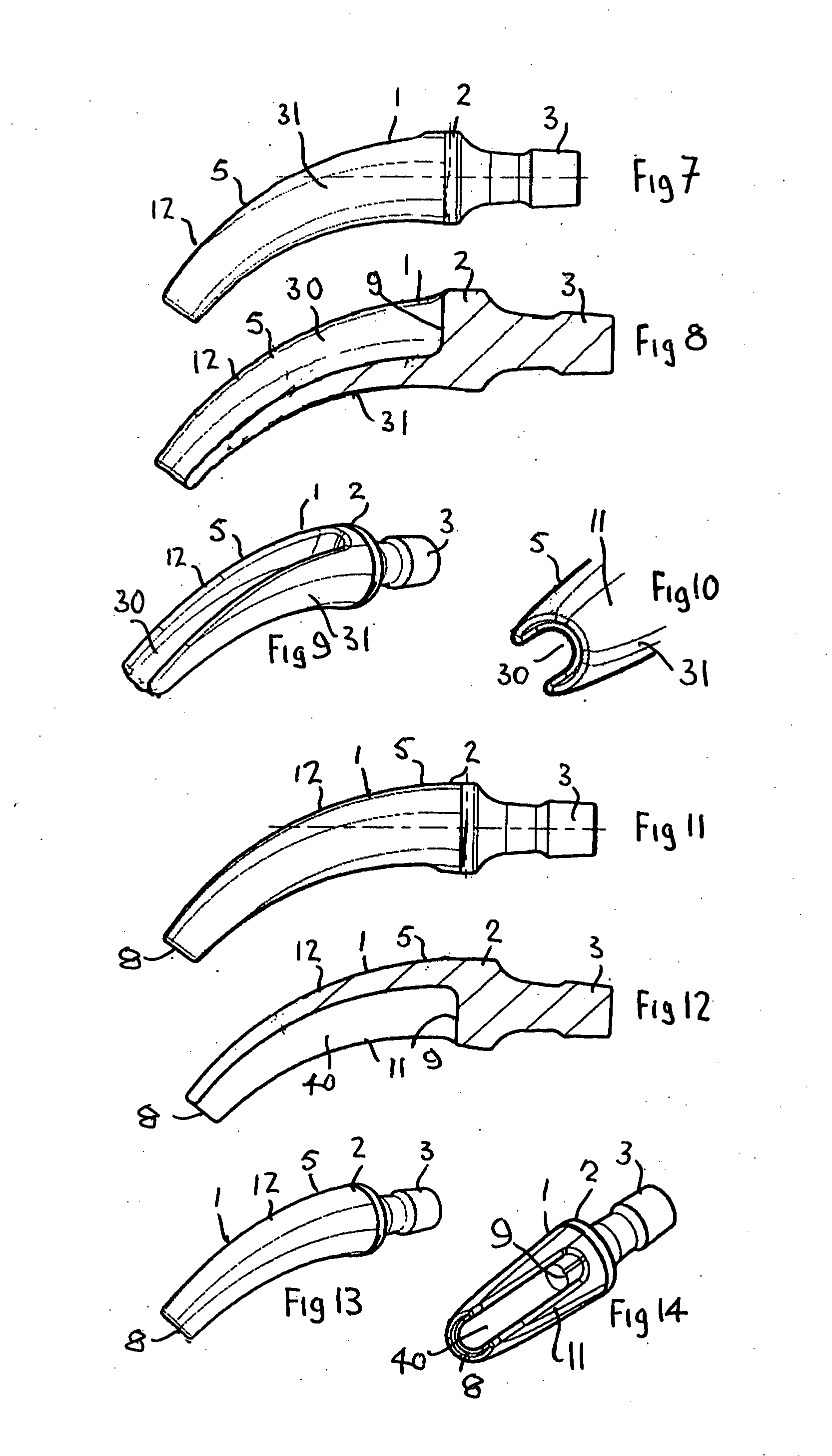
[0032]As shown in FIGS. 1, 2 and 3 a one-piece “short” femoral prosthesis 1 comprises a proximal end portion 2 which, in this embodiment, is provided with a tapered boss 3 to receive a cooperating bearing ball 4 shown in broken lines. In an alternative construction the bearing ball could be integral with the proximal end portion 2.

[0033]A gutter-shaped or U-shaped hollow stem 5 is provide which has anterior and posterior sides or legs 6 and 7 and a medial base 11, respectively, which extend from the proximal end portion 2 to an open distal end 8. The gutter shaped stem 5 is curved in a medial / lateral plane throughout its length and is closed by a substantially radially extending proximal end wall 9 adjacent the proximal end portion 2. The legs 6, 7 can be angled outwardly toward the open end of the U-shaped cross-section, for example, by 8 to 14: This angle can vary along the stem length.

[0034]As will be seen, an open topped gutter 10 is provided in the stem 5 and in this constructi...


PUM


Abstract

A prosthetic hip implant comprising: a neck portion including a prosthetic head mounted thereon; and a stem portion coupled to the neck portion having a generally u-shaped cross-section, the stem curving towards a medial side of a femur on moving in a proximal to distal direction when the stem is implanted, a base portion of the u-shaped cross-section extending between first and second legs of the u-shaped cross-section, the base portion decreasing in thickness while moving in a proximal to distal direction and a length of the first and second legs of the u-shaped cross-section decreasing on moving in a proximal to distal direction.

Description

BACKGROUND OF THE INVENTION[0001]This invention relates to a short stem prosthesis.[0002]Femoral prostheses are known which have a stem which, when fitted in a suitably prepared femur from which the head and at least part of the shoulder have been removed, extend downwards past the lesser trochanter and into the medullary canal in the shaft of the bone. Such stems can be fixed into the canal of the bone during implantation by utilizing their tapered shape by cementing or other means. Prostheses of this type are well known.[0003]Traditional neck filling stems of this type can require the removal of a large amount of trabecular bone. Stress shielding can be expected and the consequent reabsorption of the neck can endanger the stability of the stem.[0004]The present invention is intended to provide a construction which joints the concept of a proximal stem placed in the neck of the bone and following the anatomy of the boney travecular (bone sparing) and provide a design which aims to ...

Claims


Application Information

Patent Timeline
IPC IPC(8): A61F2/32A61F2/30
CPCA61F2/36A61F2310/00023A61F2002/30131A61F2002/30153A61F2002/30154A61F2002/30169A61F2002/30324A61F2002/30332A61F2002/30957A61F2002/3611A61F2002/3625A61F2002/3631A61F2002/365A61F2002/3686A61F2002/4631A61F2220/0033A61F2230/0013A61F2230/0019A61F2230/0021A61F2230/0047A61F2250/0036A61F2310/00017A61F2/3662
Inventor MERCURI, MARIOFALEZ, FRANCESCOVAIENTI, ENRICOMASSARI, LEOBENAZZO, FRANCESCOMASSE, ALESSANDRORUOSI, CARLOMARCUCCI, MASSIMILIANO
Owner BENOIST GIRARD & CIE
Why Eureka
Try Eureka