Control system

a technology of control system and control system, which is applied in the direction of program control, ratio control, special dispensing means, etc., can solve the problems of consuming energy, consuming energy, and reducing the use of water for irrigation system in agricultural, commercial, industrial, recreational or residential sites

Inactive Publication Date: 2008-05-22
WATER OPTIMIZER
View PDF30 Cites 58 Cited by
  • Summary
  • Abstract
  • Description
  • Claims
  • Application Information

AI Technical Summary

Benefits of technology

[0037]The present invention is defined by the appended claims with specific embodiments being shown in the attached drawings. For the purpose of summarizing the invention, the invention relates to a control system for regulating the flow of a liquid from a liquid provider through a liquid distribution system. The distribution system has a major liquid distribution channel and coupled to a plurality of minor liquid distribution channels for providing the flow of the liquid to a multiplicity of users. The control system comprises a plurality of controllable user valves interposed in selected ones of the multiplicity of user channels. A liquid monitor is located...

Problems solved by technology

These liquid control systems have resulted in a substantial reduction of the use of water for irrigation systems in agricultural, commercial, industrial, recreational or residential sites.
The at least one device controllably consumes energy.
Although the liquid control systems set forth in the foregoing United States patents have reduced the use of water, these liquid control systems have not addressed the problems associated with the water distribution systems between a water source and an agricultural, commercial, industrial, recreational or residential site.
The recent and substantial increase in the number of agricultural, commercial, industrial, recreational or residential sites have placed an excessive burden upon the existing distribution systems between the water source and the agricultural, commercial, industrial, recreational or residential sites.
Many of these liquid distribution systems have not been upgraded to accommodate for recent and substantial increase in the number of agricultural, commerc...

Method used


Image

  • Control system
  • Control system
  • Control system

Examples


Embodiment Construction

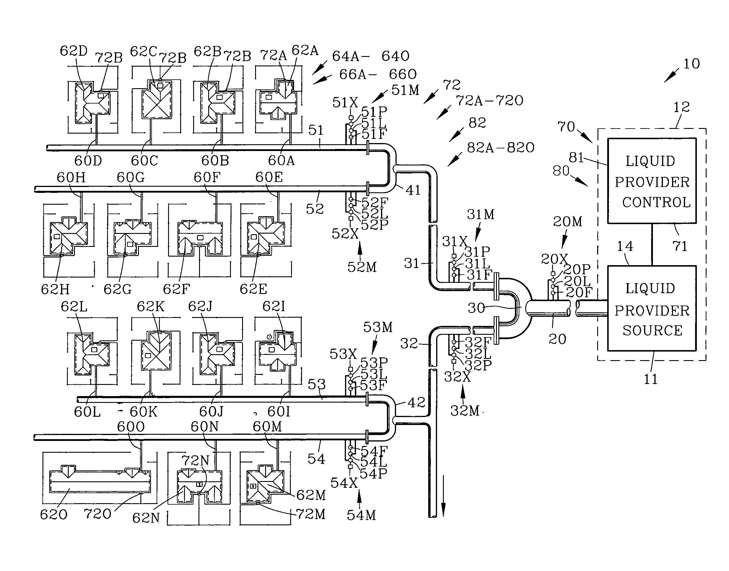
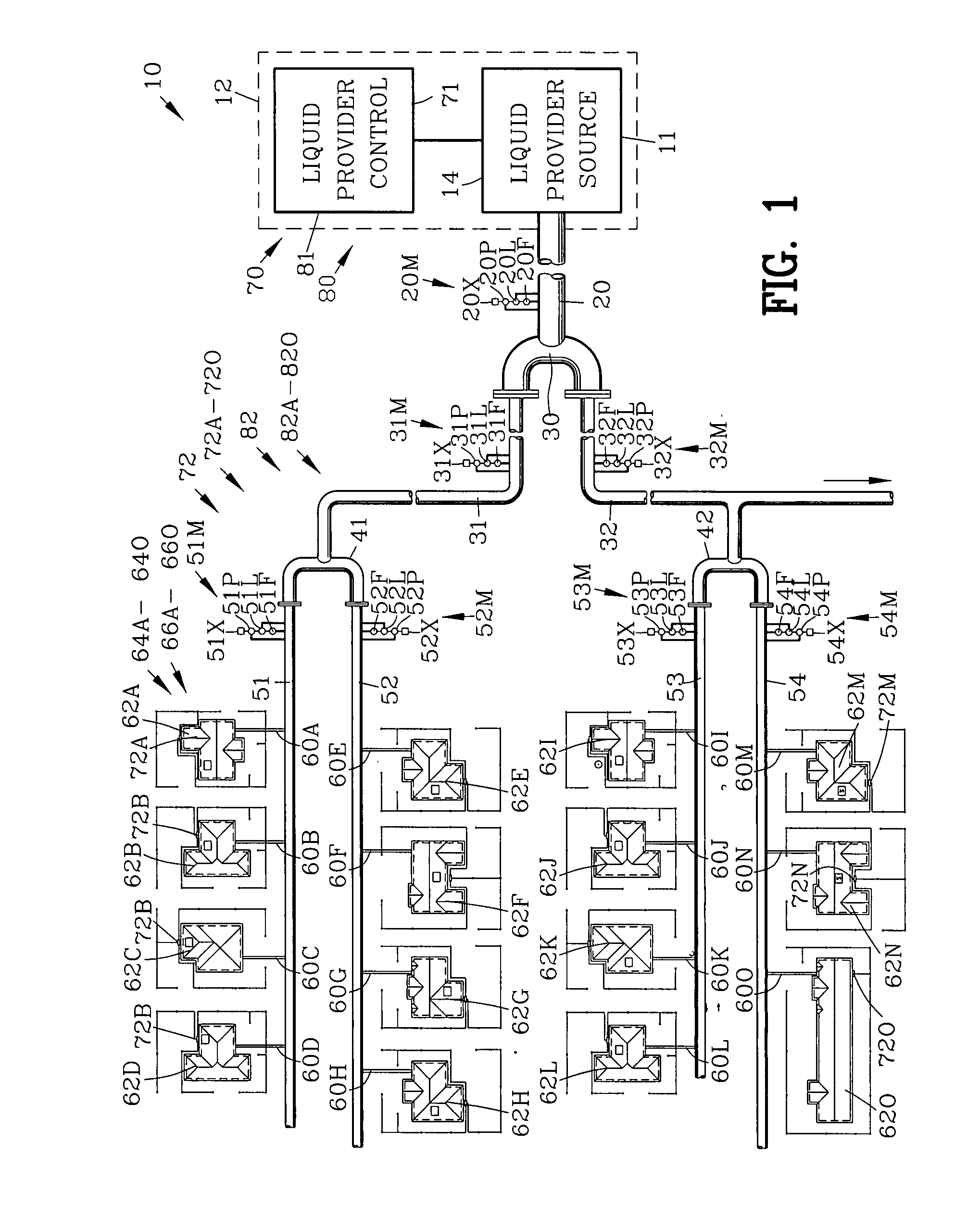
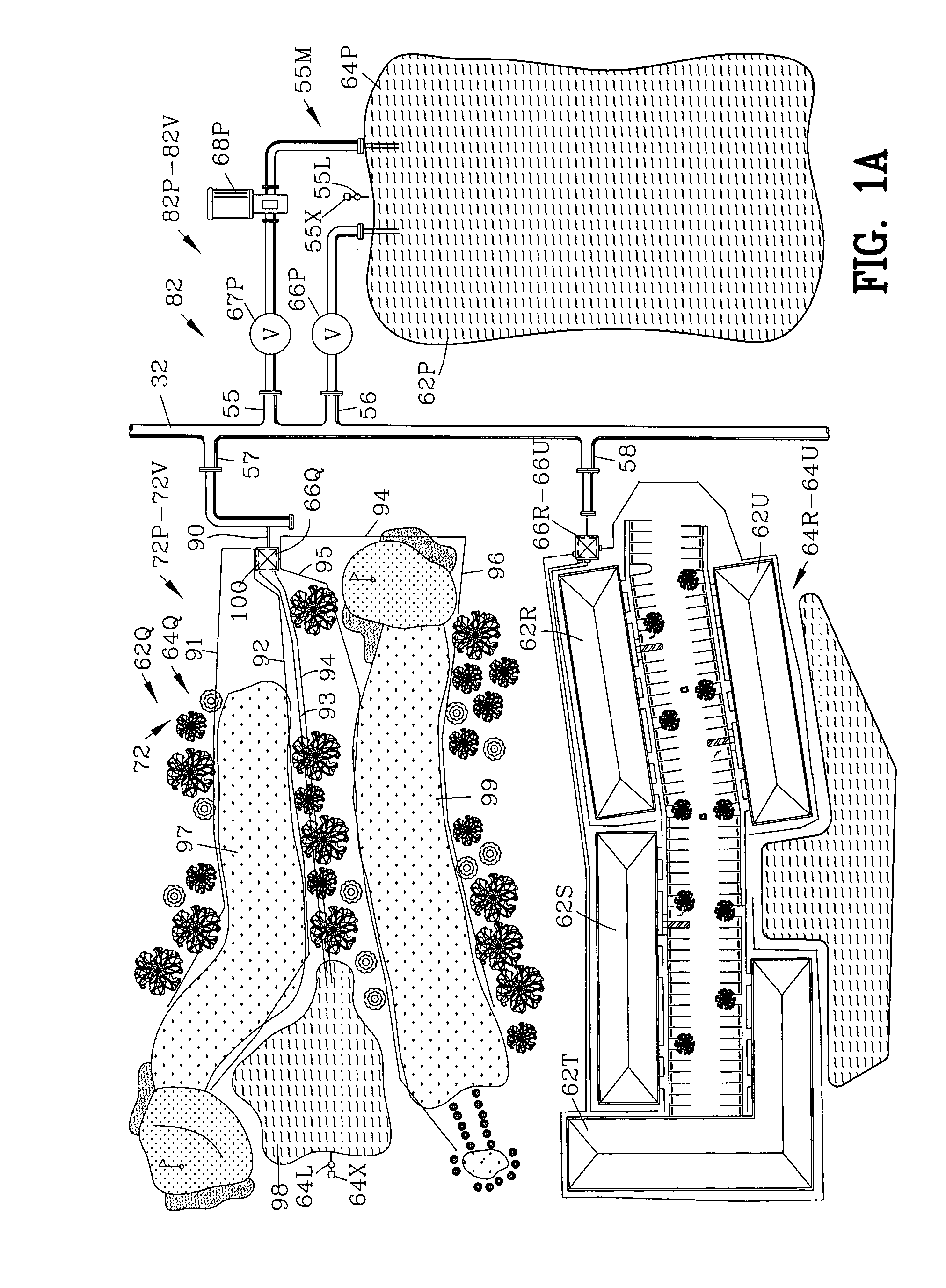
[0067]FIGS. 1 and 1A are top views of a first example of a liquid distribution system 10 for regulating the flow of a liquid 11 from a liquid provider 12 having a liquid source 14. In this example, the liquid provider 12 has been shown to be water provider 12 having a water source 14 such as a municipal water plant 12 or the like. However it should be appreciated by those skilled in the art that the present invention should not be limited to a water distribution system.

[0068]The distribution system 10 has a major liquid distribution channel 20 extending from the liquid provider 12. In this example, the major liquid distribution channel 20 is show as a liquid distribution conduit or pipe. The major liquid distribution channel 20 has a liquid monitor 20M for sensing a liquid flow characteristic within the liquid major liquid distribution channel 20. The liquid monitor 20M provides a signal output relative to the liquid flow characteristic within the major liquid distribution channels ...


PUM


Abstract

A control system is disclosed for regulating the flow of a liquid from a liquid provider through a liquid distribution system. The distribution system has a major liquid distribution channel connected to a plurality of minor liquid distribution channels providing the liquid to a multiplicity of users. A plurality of controllable user valves are interposed in the multiplicity of user channels. A liquid monitor senses a liquid flow characteristic within the liquid distribution channel. A user control changes selective controllable user valves for restoring a desired liquid flow characteristic within the liquid distribution channel.

Description

CROSS-REFERENCE TO RELATED APPLICATIONS[0001]This application claims benefit of U.S. provisional application Ser. No. 60 / 860,276 filed Nov. 20, 2006 and U.S. provisional application Ser. No. 60 / 962,325 filed Jul. 27, 2007. All subject matter set forth in U.S. provisional application Ser. No. 60 / 860,276 filed Nov. 20, 2006 and U.S. provisional application Ser. No. 60 / 962,325 filed Jul. 27, 2007 is hereby incorporated by reference into the present application as if fully set forth herein.BACKGROUND OF THE INVENTION[0002]1. Field of the Invention[0003]This invention relates to the control of liquid and more particularly to the control of fluids in a fluid distribution system.[0004]2. Background of the Invention[0005]The prior art has proposed various types of liquid control systems for controlling the flow and distribution of liquids. Some of these prior art liquid control systems relate to water control systems for controlling the flow and distribution of water. Recently, many water c...

Claims


Application Information

Patent Timeline
IPC IPC(8): G05D7/00G05B15/00
CPCA01G25/16G05D7/0664E03B7/02Y10T137/0318Y10T137/189Y10T137/0324Y10T137/86389Y10T137/7761
Inventor O'CONNOR, THOMAS M.
Owner WATER OPTIMIZER
Why Eureka
Try Eureka