Heated/cool screw conveyor

a screw conveyor and screw technology, applied in the field of screw conveyors, can solve the problems of affecting the efficiency of cleaning, affecting the cleaning effect, and consuming so much volume that the screw must be removed for cleaning, and achieves the effect of uniform temperature and particularly thermal efficiency

Inactive Publication Date: 2008-05-29
ESTERSON CHRISTOPHER +1
View PDF60 Cites 37 Cited by
  • Summary
  • Abstract
  • Description
  • Claims
  • Application Information

AI Technical Summary

Benefits of technology

[0005]A further object of this invention is to provide such a heated / cooled screw conveyor which is particularly thermally efficient and which provides for a more uniform temperature throughout the heated / cooled zone.

Problems solved by technology

Carbon black pellets are extremely small and fragile.
Over time a build up of carbon black fines develops on the screw of the conveyor and eventually takes up so much volume that the screw must be removed for cleaning.
Depending on the volume of carbon black moved through the screw this could be done several times per year at great expense due to labor and lost production.
This method is only about 40% efficient, meaning that to achieve a screw temperature of 100° C. requires a heater temperature of 250° C. The thermal profile of the heated screw is also not uniform.
The uneven thermal profile can result in fines building up at the in-feed and discharge ends of the screw.
Additionally, because the cartridge heater does not rotate with the screw the heater is subject to wear and vibration that shortens its useful life.
The result is an expensive system both in initial cost and in the cost of operation and maintenance, The cost of down time from carbon black fines outweighs these costs in high volume production but smaller volume rubber mixing operations may not see a fast enough return on their investment.
Similar problems exist where screw conveyors, such as an auger screw, are used in applications involving cooling below ambient temperature.

Method used


Image

  • Heated/cool screw conveyor
  • Heated/cool screw conveyor
  • Heated/cool screw conveyor

Examples


Embodiment Construction

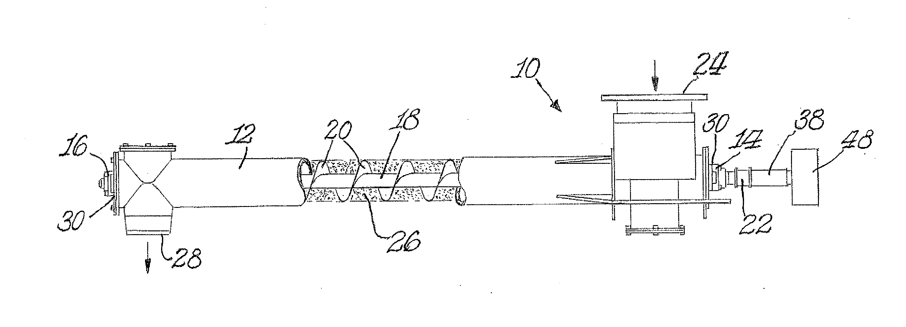
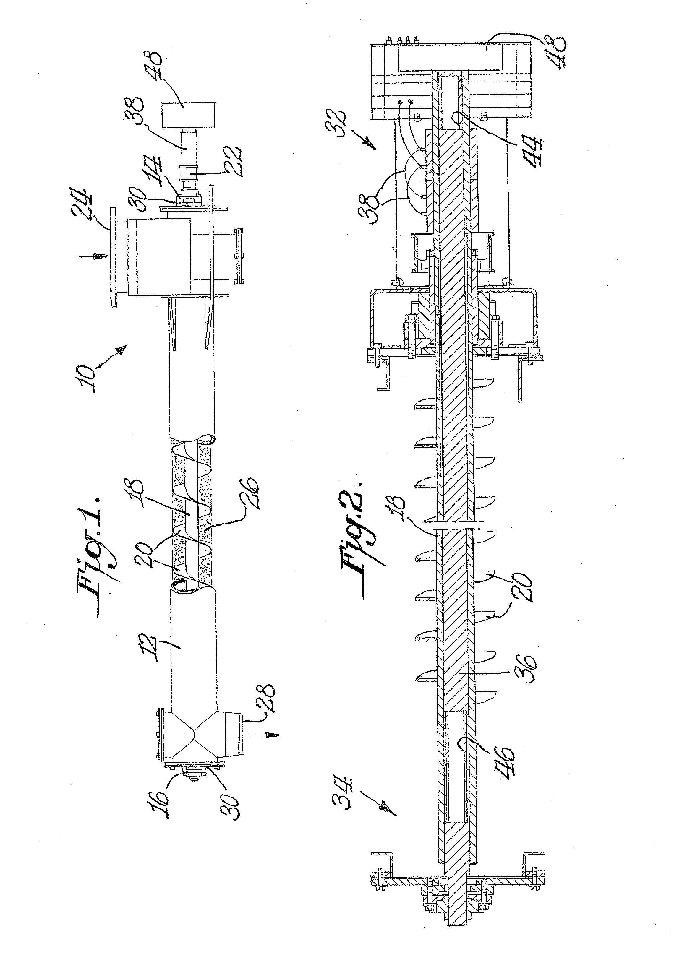
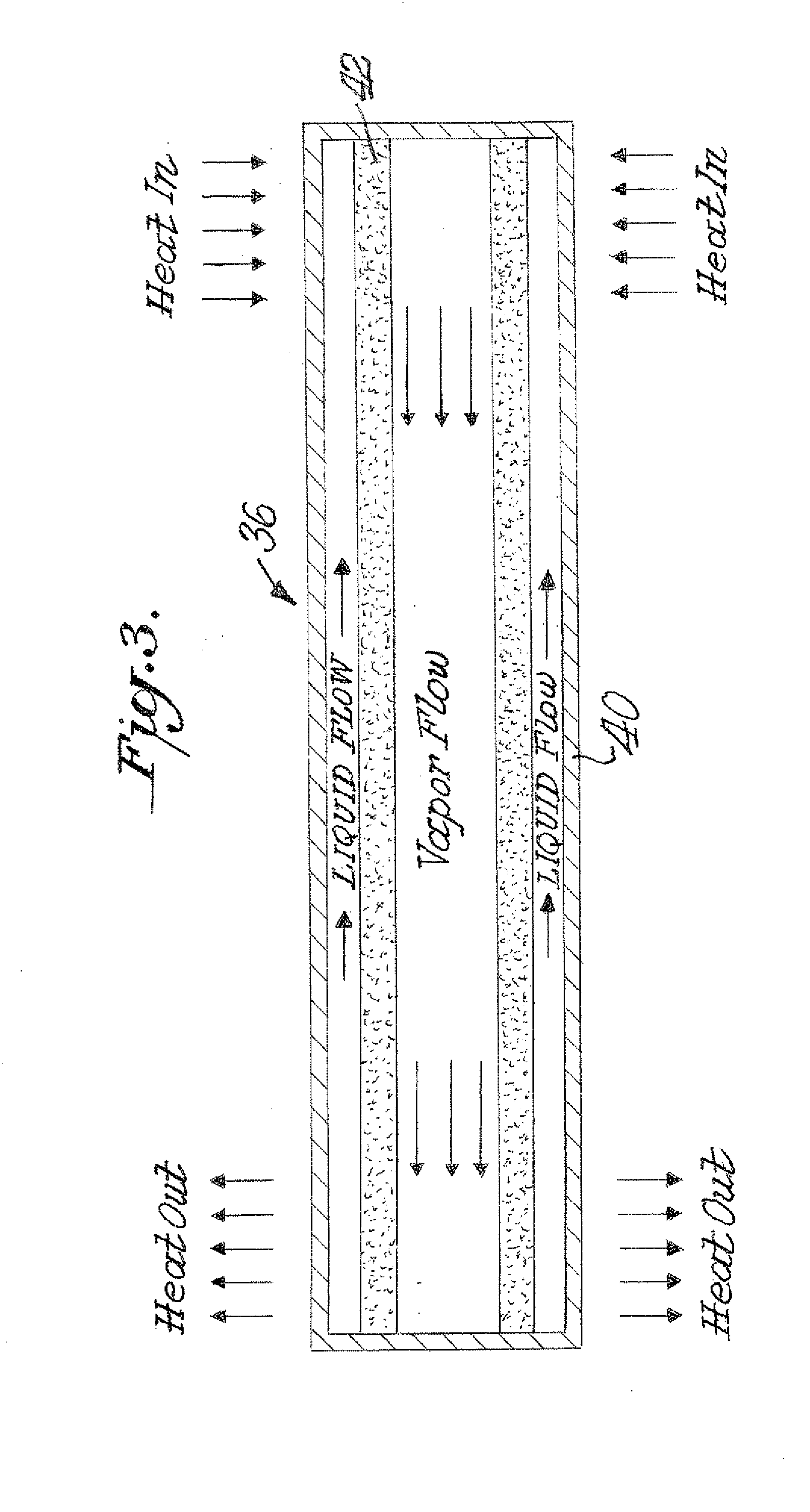
[0011]The present invention addresses problems relating to the inefficiency and high operating costs of conventional heated screw conveyors. A key feature of the invention is the use of a thermosyphon to heat the screw instead of using a cartridge heater. The thermosyphon in the preferred practice of the invention is an integral part of the screw shaft rotating with the screw shaft and transferring heat by conduction through direct contact rather than radiation. The thermosyphon works on the principle of latent heat of evaporation. Since the latent heat of evaporation is large the thermosyphon has the capacity to transfer large amounts of heat at high speeds in both heating and cooling operations. Therefore a small heated section of thermosyphon will transfer the heat / cold along its entire length rapidly and efficiently. Theoretically the thermosyphon will be 2.5 times more efficient than conventional cartridge heater designs. The thermosyphon design will also heat / cold the screw un...


PUM


Abstract

A screw conveyor includes a hollow rotatable shaft having an externally mounted flight extending along a portion of its length. Thermal applicating structure is provided at one end of the shaft for heating or cooling the screw conveyor. A thermosyphon is mounted within the shaft. The thermosyphon includes a hollow tube mounted against and in direct surface to surface contact with the shaft to rotate co-jointly with the shaft.

Description

BACKGROUND OF THE INVENTION[0001]There are various applications of screw conveyors which are heated or cooled depending on the intended purpose. In one such application carbon black pellets are conveyed for use in rubber compounding. A preferred form of conveyance is a screw conveyor because the conveyor also acts as a feeder capable of delivering precise amounts of carbon black to a weigh hopper. Carbon black pellets are extremely small and fragile. The rubber mixing process is generally a batch operation requiring the movement of large volumes of carbon black in an intermittent fashion. As the carbon black is shuttled through the process some portion of the fragile pellets break down and become micron size particles of dust known as fines. Carbon black fines have an affinity for anything they come in contact with including themselves. Over time a build up of carbon black fines develops on the screw of the conveyor and eventually takes up so much volume that the screw must be remov...

Claims


Application Information

Patent Timeline
Patent Type & Authority Applications(United States)
IPC IPC(8): B65G33/00B65G33/24F27D3/08
CPCF27D3/08B65G33/24
Inventor ESTERSON, CHRISTOPHERWALINSKAS, KARL
Owner ESTERSON CHRISTOPHER
Why Eureka
Try Eureka