Compact LED with a self-formed encapsulating dome

a self-formed, compact led technology, applied in the direction of solid-state devices, basic electric elements, electric devices, etc., can solve the problem of cost and other issues of primary concern

Active Publication Date: 2008-05-29
AVAGO TECH INT SALES PTE LTD
View PDF2 Cites 38 Cited by
  • Summary
  • Abstract
  • Description
  • Claims
  • Application Information

AI Technical Summary

Problems solved by technology

For lighting applications, cost is also of primary concern.
However, providing a reproducible encapsulation structure that does not entail utilizing some form of separate containment dam to prevent the silicone from spreading before it sets remains a challenge in light sources that do not utilize a reflector cup around the LED.

Method used


Image

  • Compact LED with a self-formed encapsulating dome
  • Compact LED with a self-formed encapsulating dome
  • Compact LED with a self-formed encapsulating dome

Examples


Embodiment Construction

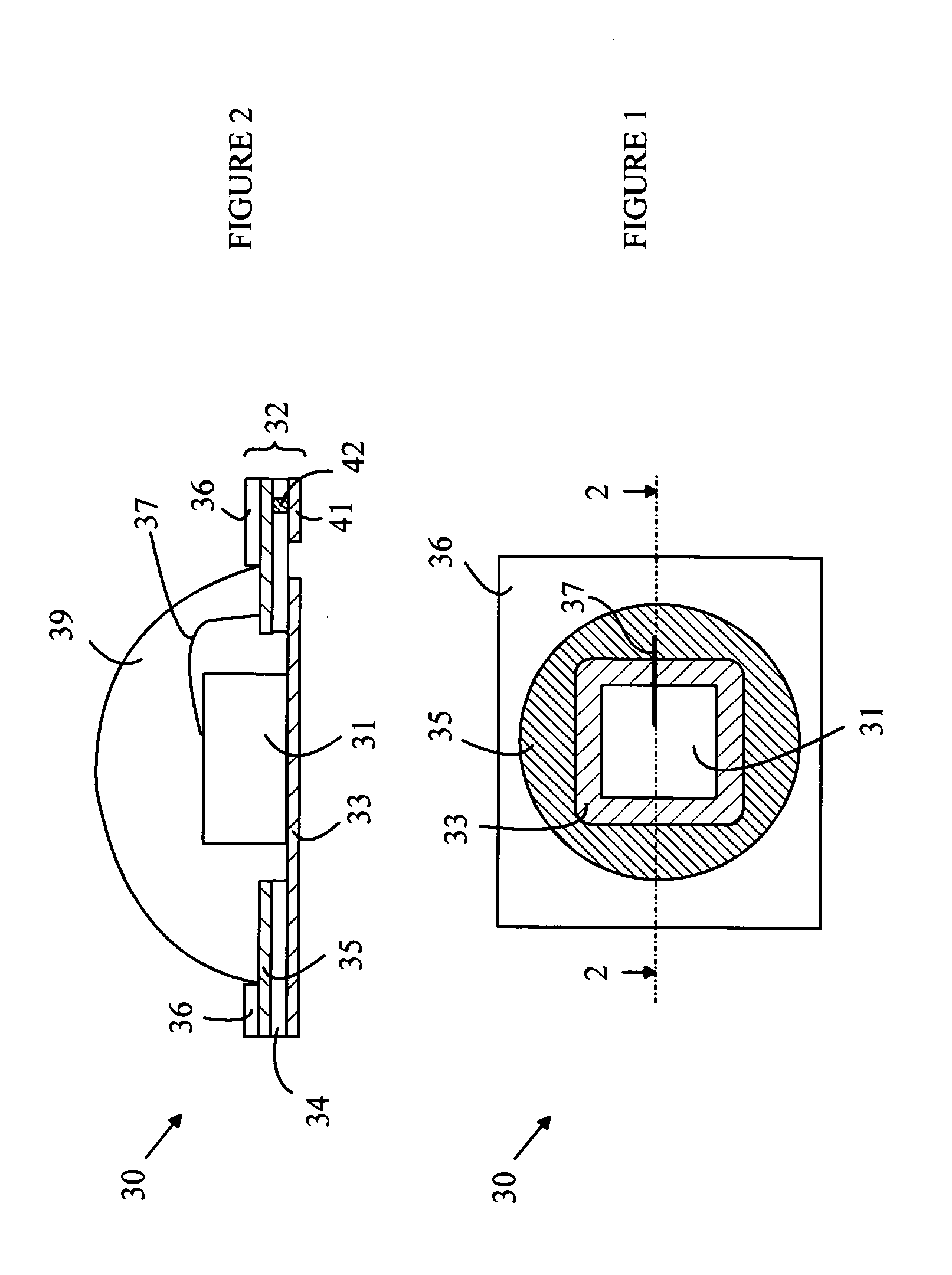
[0018]The manner in which the present invention provides its advantages can be more easily understood with reference to FIGS. 1 and 2, which illustrate a light source according to one embodiment of the present invention. FIG. 1 is a top view of light source 30, and FIG. 2 is a cross-sectional view of light source 30 through line 2-2 shown in FIG. 1. Light source 30 utilizes a die 31 that contains an LED. Die 31 is mounted on a carrier 32 and covered with an encapsulating dome 39.

[0019]Carrier 32 is constructed from an insulating substrate 34 that has two layers of metal deposited on opposite sides of substrate 34. Both of these layers are patterned to provide the various traces needed to connect and power die 31. Die 31 is mounted on and, connected electrically to, a pad on layer 33, which is used to provide one of the power connections to die 31. The other power terminal of die 31 is on the top of die 31 and is connected to a trace on layer 35 by a wire bond 37. This trace is conne...


PUM

PropertyMeasurementUnit
thicknessaaaaaaaaaa
thicknessaaaaaaaaaa
thicknessaaaaaaaaaa

Abstract

A light source including a die, substrate, and droplet of encapsulating material is disclosed. The die includes a semiconductor light-emitting device that is connected to first and second conducting traces on a first surface of the substrate. The droplet of encapsulant material overlies the die and is formed from a liquid precursor material that is characterized by a surface tension. The droplet has a periphery in contact with the first surface, the periphery having a shape determined by a predefined feature on the first surface and the surface tension of the liquid precursor material. The feature can include a recess in the first surface or a ring having an area that is raised above the first surface.

Description

BACKGROUND OF THE INVENTION[0001]Light emitting diodes (LEDs) are replacing conventional light sources such as fluorescent and incandescent light bulbs in many applications. LEDs have similar electrical efficiency and longer lifetimes than fluorescent light sources. In addition, the driving voltages needed are compatible with the battery power available on many portable devices.[0002]An LED light source typically includes one or more semiconductor dies that are mounted on a substrate that provides the power to the LED and a structure that can be utilized to mount the light source on the appropriate surface of the final product in which the light source is to function. For a number of reasons, the LED is typically covered with an encapsulating layer that has a spherical outer surface. First, the die must be protected from the environment.[0003]Second, some light sources utilize a layer of phosphor that converts all or a portion of the light from the LED to light having a different sp...

Claims


Application Information

Patent Timeline
Patent Type & Authority Applications(United States)
IPC IPC(8): H01L23/29
CPCH01L33/486H01L33/52H01L33/54H01L24/97H01L2224/97H01L2224/85
Inventor PANG, SIEW IT
Owner AVAGO TECH INT SALES PTE LTD
Why Eureka
Try Eureka