
Device for affixing to cylindrical components of medical instruments

a technology for cylindrical components and clamping devices, which is applied in the direction of mechanical equipment, applications, manufacturing tools, etc., can solve the problems of affecting the operation of eccentric tappet levers, affecting the operation of clamping devices, and affecting the operation of the eccentric tappet lever, etc., and achieves the effect of simple manufacturing and operation

Active Publication Date: 2008-05-29
KARL STORZ GMBH & CO KG
View PDF12 Cites 9 Cited by
  • Summary
  • Abstract
  • Description
  • Claims
  • Application Information

AI Technical Summary

Benefits of technology

[0007]The use of this slider for reversible transfer of the collet chuck from the open to the clamping position constitutes an especially simple and quickly managed displacement possibility for affixing a component in secure stationary manner, secure against rotation, on the cylindrical component.
[0008]By configuring the clamping element of the intake part as a sleeve-shaped collet chuck that surrounds the cylindrical component essentially coaxially, it becomes possible to distribute the clamping force exerted on the cylindrical component by configuring an axially extending surface pressure over the entire periphery of the cylindrical component in such a way that no inward-pressing or tapering local clamping occurs.
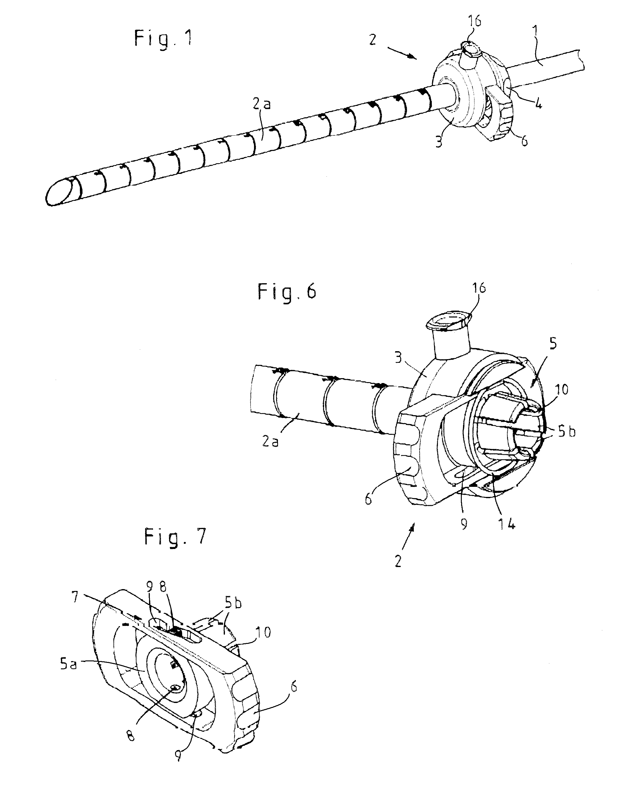
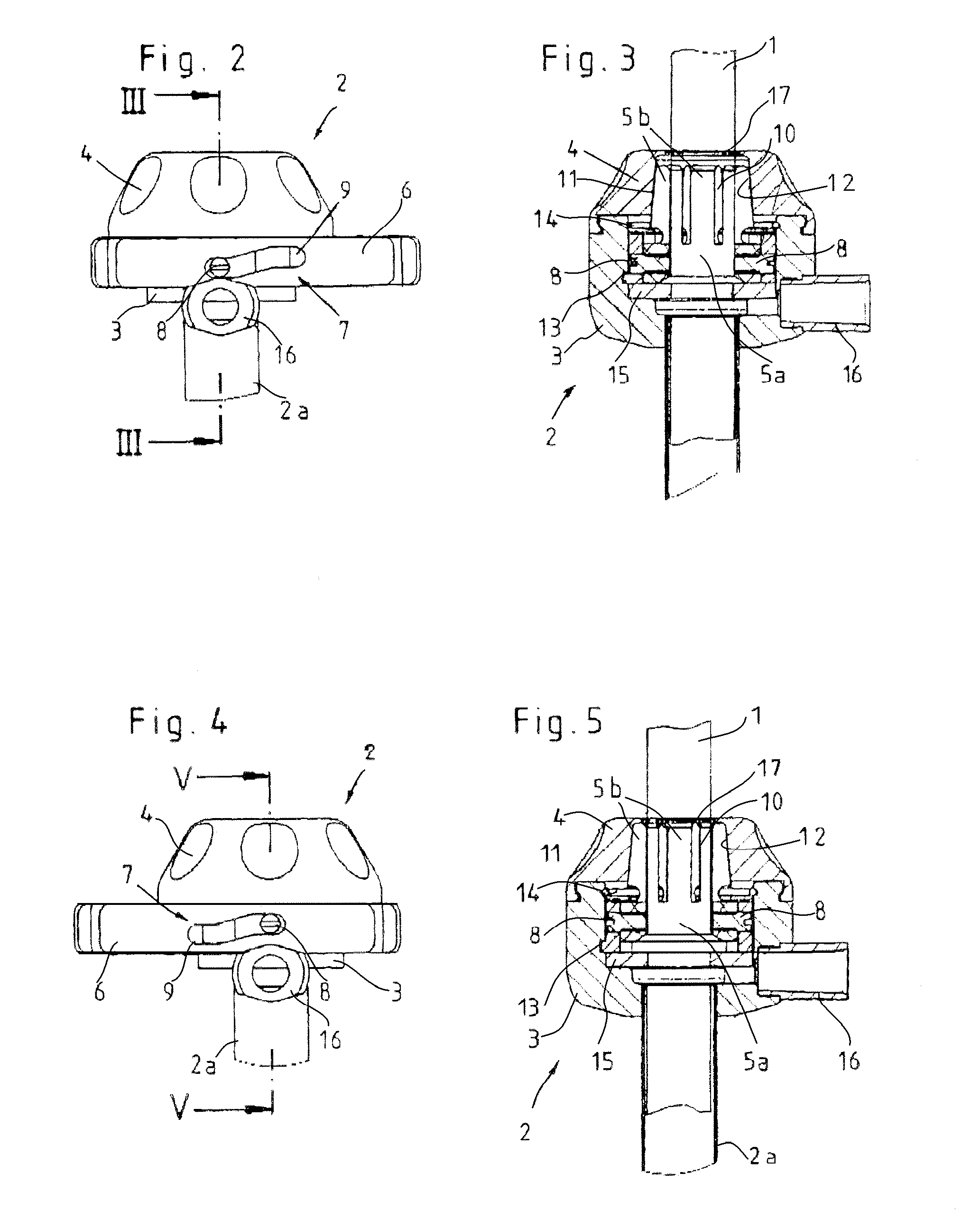
[0010]According to a preferred embodiment of the invention it is proposed that for reversible transfer of the collet chuck from open to clamping position, the collet chuck and slider are in active connection to one another by way of a mortise-and-tenon control, whereby the mortise-and-tenon control preferably consists of at least one control pin that is mounted on the collet chuck and engages in a guide track configured in the slider. Mortise-and-tenon controls are characterized in that, in addition to simplicity in manufacture, they ensure a reliable switching of the components that they propel.
[0013]According to a preferred embodiment of the invention it is proposed that the clamping effect of the collet chuck is produced when the a cone is configured on the collet chuck that can be brought into active connection with a counter-cone configured in the housing of the intake part, so that the collet chuck preferably can be slid axially by means of the at least one guide mortise mounted in the guide track of the slider in such a way that the cone of the collet chuck can be displaced between a position contiguous with the counter-cone of the housing and a position that releases the counter-cone of the housing.
[0014]The configuration of the components that produce the actual clamping effect as cone and counter-cone constitutes an embodiment that is simple to manufacture and to operate. The collet chuck, which includes the cone, is pressed against the counter-cone by the mortise-and-tenon control upon closing of the clamping connection and it is drawn away from the counter-cone upon releasing the clamping connection.

Problems solved by technology

The disadvantage in clamping devices known in the art is that, because of the configuration of the clamping mechanism, there is a risk that the cylindrical component to which the clamping device is to be attached will be damaged.
This risk is especially present when the cylindrical component is an optic system or the shaft tube of the lens system.
This clamping mechanism has proven itself in the art, but the actuation of the eccentric tappet lever can require considerable force, in particular with large shaft diameters.

Method used


Image

  • Device for affixing to cylindrical components of medical instruments
  • Device for affixing to cylindrical components of medical instruments
  • Device for affixing to cylindrical components of medical instruments

Examples


Embodiment Construction

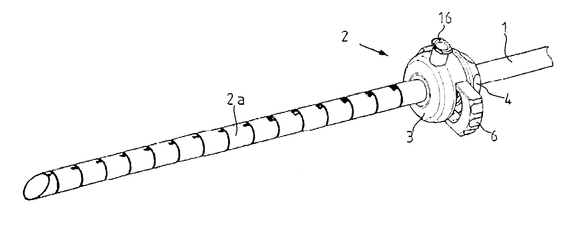
[0026]The device illustrated in FIGS. 1 through 7 for affixing medical instruments onto cylindrical components 1, such as instrument shafts or optical systems of endoscopic instruments, consists essentially of an intake part 2 that can be mounted on the cylindrical component 1 and in which the actual clamping mechanism is positioned. The intake part 2 consists, as can be seen in particular from FIGS. 3 and 5, of a housing 3 that can be closed by means of a cover cap 4.

[0027]Claming devices of this type are used in order to secure other components, such as handgrips, guides, or even medical instruments, to a medical instrument.

[0028]In the illustrated embodiment, the intake part 2 includes an applied outer tube 2a for inserting the cylindrical component 1 that is to be affixed. It is also possible, of course, to configure the intake part without this outer tube 2a, so that the cylindrical component 1 that is to be affixed extends in the longitudinal direction through the intake part ...


PUM


Abstract

The invention relates to a device for affixing to cylindrical components of medical instruments, for instance an instrumental shaft, having at least one intake part that can be mounted on the cylindrical component and can be affixed to the cylindrical component, wherein a sleeve-shaped collet chuck that essentially coaxially surrounds the cylindrical component is positioned in the intake part and whose inner diameter can be displaced between a span that can slide along the cylindrical component and a span that is in form-locking contiguity on the cylindrical component. To allow for a stationary clamping on the one hand and ensure a non-harmful clamping of the cylindrical component on the other hand, it is proposed with the invention that the inner diameter of the collet chuck can be displaced by a slider that can slide essentially diagonally to the cylindrical component and is mounted so that it can slide in the housing of the intake part.

Description

CROSS-REFERENCE TO RELATED APPLICATIONS[0001]The present application claims priority of German patent application No. 10 2006 055 172.9 filed on Nov. 23, 2006, the content of which is incorporated herein by reference.FIELD OF THE INVENTION[0002]The invention relates to a device for affixing to cylindrical components of medical instruments, for instance an instrument shaft, having at least one intake part that can be positioned on the cylindrical component and can be affixed to the cylindrical component, wherein there is positioned in the intake part a sleeve-shaped collet chuck that essentially coaxially surrounds the cylindrical component and whose inner diameter can be displaced between a span that can move along the cylindrical component and a span that is essentially in form-locking contiguity with the cylindrical component.BACKGROUND OF THE INVENTION[0003]Clamping devices of this type are used in order to affix other components such as handgrips, guides, or medical instruments ...

Claims


Application Information

Patent Timeline
Patent Type & Authority Applications(United States)
IPC IPC(8): B23Q3/06
CPCA61B1/00135A61B17/3421A61B2017/0046Y10T279/17529A61B2017/347Y10T279/17341Y10T279/17905A61B2017/00477
Inventor FREY, SEBASTIANSAUER, MICHAEL
Owner KARL STORZ GMBH & CO KG
Learn More