Inflator with an auto-ignition cradle

a technology of auto-ignition and inflator, which is applied in the direction of pedestrian/occupant safety arrangement, vehicle components, vehicular safety arrangements, etc., can solve the problems of safety concerns, insufficient exposure of auto-ignition composition to the booster, etc., and achieve rapid and substantially uniform heating of the booster composition, facilitates assured contact, and efficiently brought to combustion

Inactive Publication Date: 2008-05-29
TK HLDG
View PDF11 Cites 8 Cited by
  • Summary
  • Abstract
  • Description
  • Claims
  • Application Information

AI Technical Summary

Benefits of technology

[0004]An inflator is provided that responds to the above-referenced concerns by employing an auto-ignition assembly or cradle that facilitates assured contact between the auto-ignition composition and the booster composition. The auto-ignition cradle is designed to advantageously utilize a thermodynamic relationship between the housing or exterior of the inflator, and the cradle itself. As such, the auto-ignition cradle in an operative state thermodynamically communicates with the housing of the inflator or directly with the exterior of the inflator. Once heat surrounding the inflator reaches a predetermined threshold temperature, the auto-ignition cradle in thermodynamic communication with that heat, provides assured ignition of the auto-ignition composition that alternatively provides rapid and substantially uniform heating of the booster composition.
[0005]The present invention therefore, includes an inflator that contains an auto-ignition cradle extending within an interior of the inflator. An auto-ignition composition is housed within the cradle and held there by a bias provided by the design of the cradle. A booster composition is intimately exposed to the auto-ignition material whereby once the cradle is heated to produce ignition of the auto-ignition composition, the booster composition is efficiently brought to combustion thereby also efficiently bringing the main gas generant composition to combustion prior to any substantial melt of the gas generant composition.

Problems solved by technology

In some inflators, the auto-ignition composition may not provide sufficient exposure to the booster propellant to ensure sufficient ignition of the main gas generant in accordance with improving the safety of the inflator.
In the absence of an effective auto-ignition mechanism, the main gas generant in its melt phase could potentially provide an overly energetic system thereby resulting in safety concerns.

Method used


Image

  • Inflator with an auto-ignition cradle
  • Inflator with an auto-ignition cradle
  • Inflator with an auto-ignition cradle

Examples


Embodiment Construction

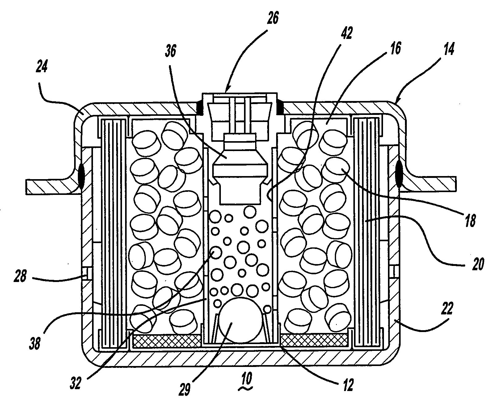
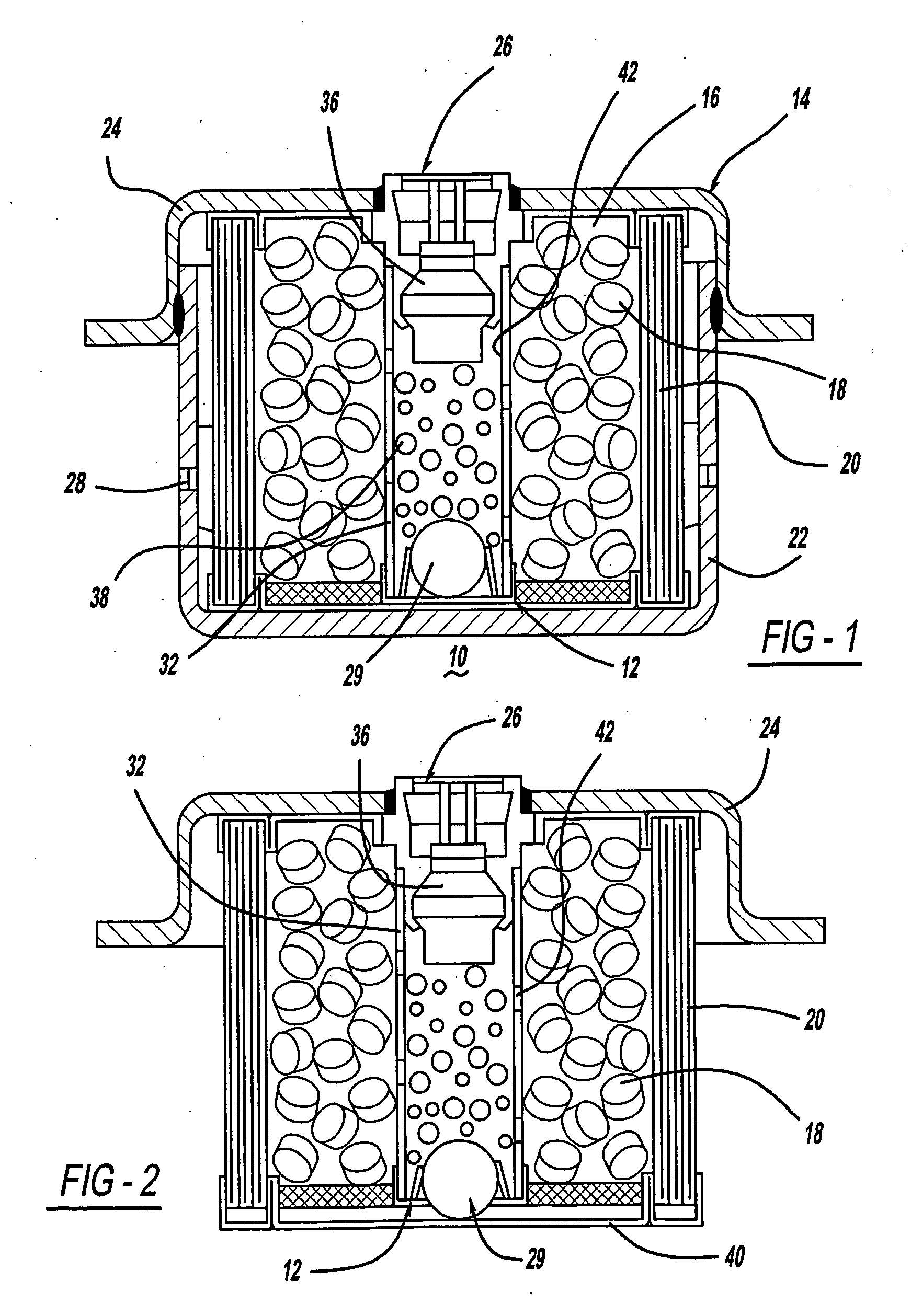
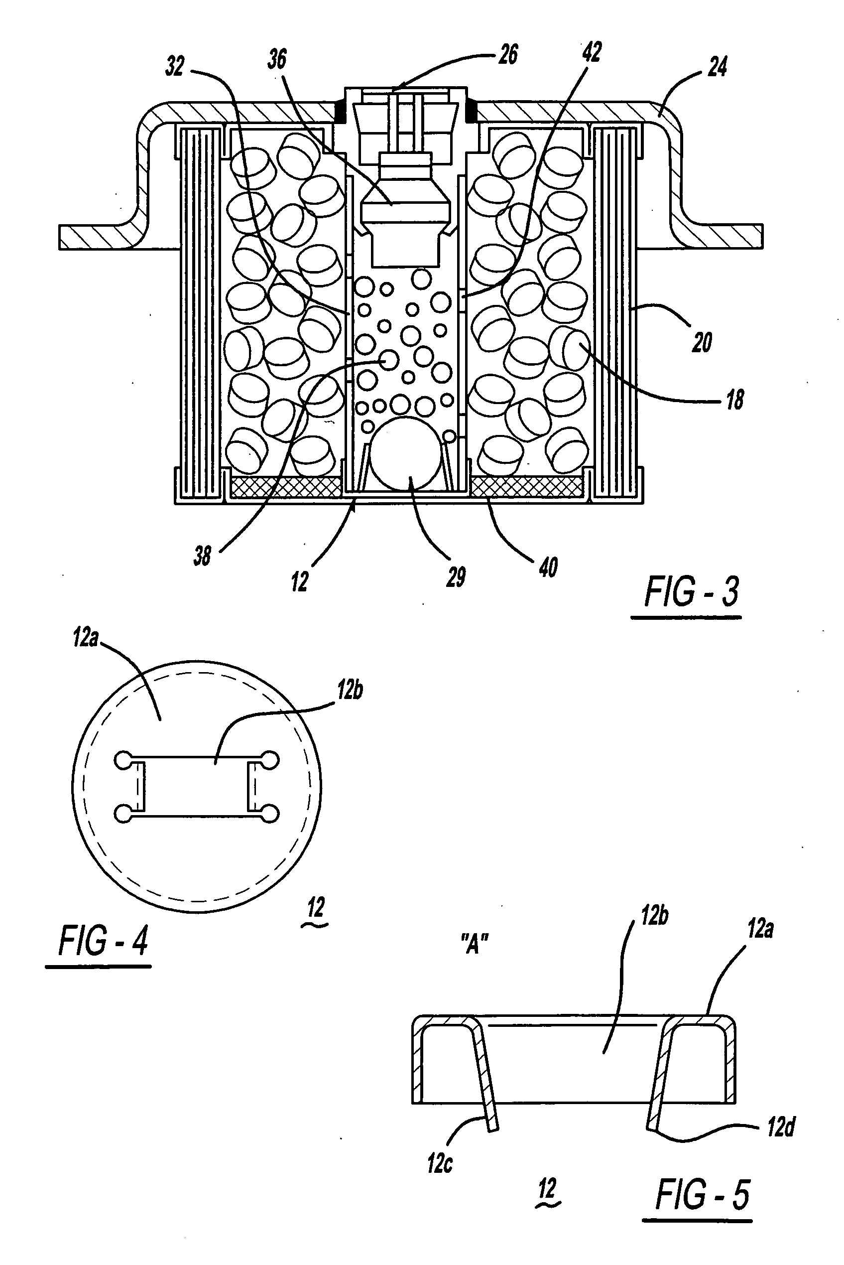
[0011]A gas generating system includes an inflator that contains an auto-ignition cradle containing an auto-ignition composition. The cradle operatively and thermodynamically communicates with the exterior of the inflator and also resiliently contains the auto-ignition composition, thereby maximizing the ignitability of the auto-ignition composition in the event of a fire.

[0012]FIGS. 1-3 show an inflator 10 incorporating an auto-ignition cradle 12 in accordance with the present invention. Inflator 10 may be utilized, for example, as a driver side inflator for inflating a driver side airbag. As seen in FIGS. 1-3, inflator 10 includes a housing 14, an annular propellant chamber 16, a quantity of a gas generant material 18 positioned in propellant chamber 16, and an annular filter 20 enclosing propellant chamber 16. Inflator housing 14 is formed by bonding or welding together a first housing portion 22 and a second housing portion 24 in a nested relationship. Second housing portion 24 ...


PUM


Abstract

A gas generating system includes an inflator that contains an auto-ignition cradle containing an auto-ignition composition. The cradle operatively and thermodynamically communicates with the exterior of the inflator and also resiliently contains the auto-ignition composition, thereby maximizing the ignitability of the auto-ignition composition in the event of a fire.

Description

CROSS REFERENCE TO RELATED APPLICATIONS[0001]This application claims the benefit of provisional application Ser. No. 60 / 860,701 filed on Nov. 22, 2006.BACKGROUND OF THE INVENTION[0002]The present invention relates to gas generating systems and, more particularly, to an gas generating system for inflating an inflatable element of a vehicle occupant protection system, the gas generating system incorporating an assembly for housing an auto-ignition composition in intimate contact with the booster composition.[0003]Many inflators incorporate auto-ignition compositions that provide enhanced safety of the gas generator / inflator in the event of a fire during shipping or storage of the Vehicle, for example, or during any car fire. Typically, the auto-ignition composition is formulated to auto-ignite at temperatures below the melting point of the other compositions associated with the inflator, including the booster composition and the main gas generating composition. In some inflators, the ...

Claims


Application Information

Patent Timeline
Patent Type & Authority Applications(United States)
IPC IPC(8): B60R21/264
CPCB60R21/2644B60R2021/2648B60R2021/26064
Inventor DOMAZET, SLAVENQUIOC, EDUARDO L.BURNS, SEAN P.
Owner TK HLDG
Why Eureka
Try Eureka