

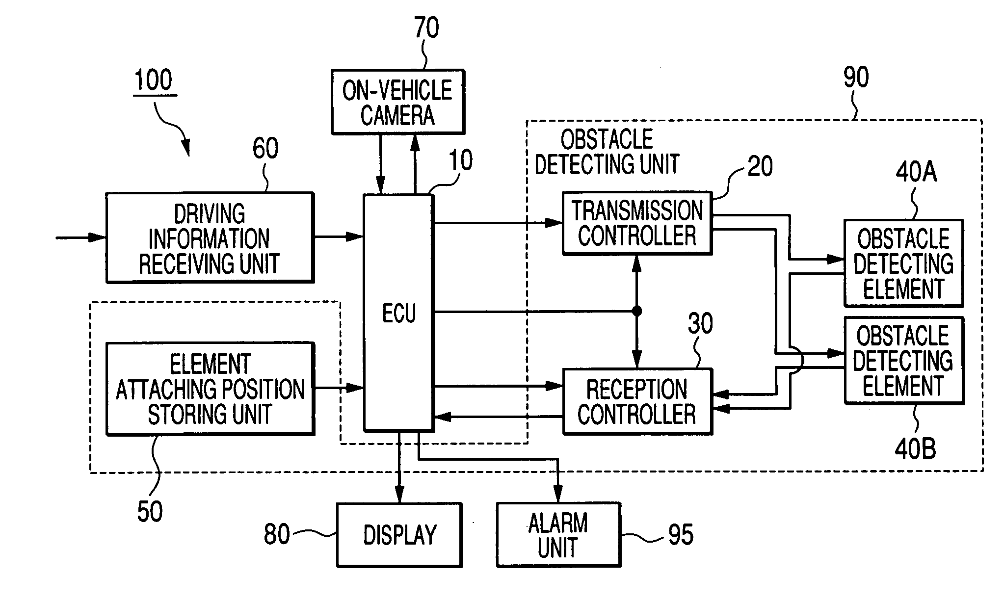
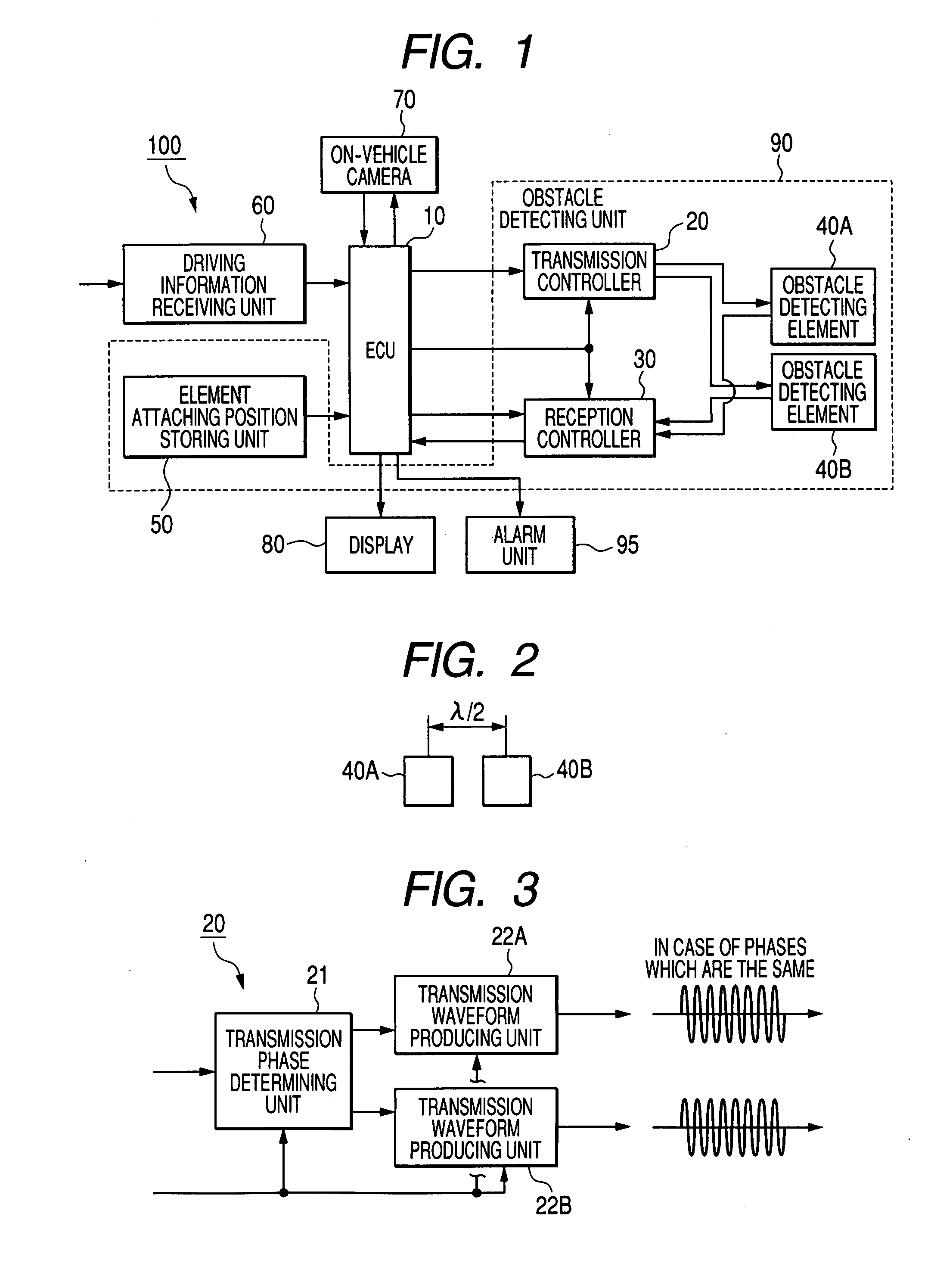
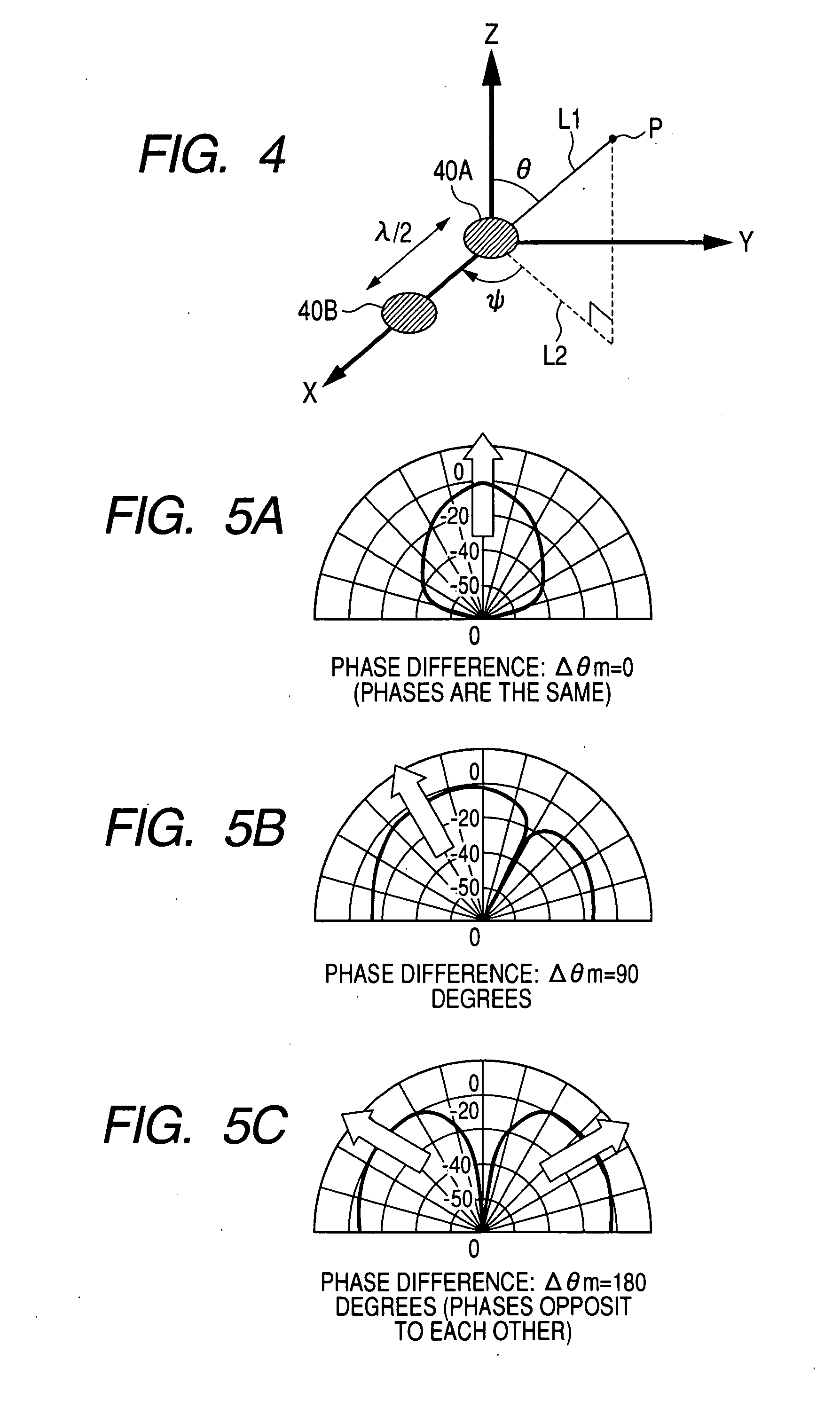
Driving support apparatus
a technology of supporting apparatus and driver, which is applied in the direction of non-deflectable wheel steering, underwater vessels, electric devices, etc., can solve the problems of difficult recognition of the movement of the vehicle from an image, difficult for the driver to correctly recognize the short distance between the vehicle and the obstacle, and easy misjudgment of the vehicle to run straight, etc., to achieve high precision
- Summary
- Abstract
- Description
- Claims
- Application Information
AI Technical Summary
Benefits of technology
Problems solved by technology
Method used
Image

Examples
embodiment 1
Modification of Embodiment 1
[0120]In this modification, the ECU 10 controls the camera 70 to photograph an obstacle such as another vehicle, and the ECU 10 produces a bird's-eye view of the obstacle photographed by the camera 70. The unit 90 is not used, so that no obstacle detecting marks are indicated on the display 80. A technique of displaying a bird's-eye view of an object photographed by an on-vehicle camera is well known. For example, this technique is disclosed in Published Japanese Patent First Publication No. H10-211849, so that the technique is not described in more detail.
[0121]FIG. 16 shows an image of a vehicle figure of a present vehicle shown in FIG. 14A and photographed by an on-vehicle camera. A present vehicle intends to park in series to another vehicle, and real conditions of these vehicles are shown in FIG. 14A. A vehicle figure 110 of the present vehicle is shown in a bird's-eye view.
[0122]An external shape 130 of another vehicle shown in a bird's-eye view in ...
embodiment 2
[0124]In this embodiment, the ECU 10 produces a repetitive figure and controls the display 80 to draw the repetitive figure such that the repetitive figure is superimposed on the vehicle figure 110 of the image shown on the display 80 and is moved in accordance with a running speed and a steering angle of the present vehicle. The repetitive figure is formed of a plurality of predetermined figures repeatedly arranged at equal intervals along each of longitudinal and lateral directions of the image. A grid figure represents the repetitive figure. This grid figure is formed of a plurality of longitudinal lines arranged at equal intervals and a plurality of lateral lines arranged at equal intervals.
[0125]FIG. 17 is an image of a grid figure superimposed on the vehicle figure 110. A grid figure 146 shown in FIG. 17 is moved relative to the vehicle figure 110 in accordance with a running speed and a steering angle of the present vehicle received in the unit 60, while the vehicle figure 11...
embodiment 3
[0130]In this embodiment, the ECU 10 produces an enlarged image and a wider-area image and controls the display 80 to display the enlarged image with the wider-area image. The enlarged image includes at least one of obstacle detecting marks P, a portion of a vehicle figure 110 and a predicted running locus 120 of which sizes are enlarged. The wider-area image includes the whole vehicle figure 110, obstacle detecting marks P and the running locus 120.
[0131]FIG. 19 shows an enlarged image and a wider-area image simultaneously displayed on the display 80. As shown in FIG. 19, a wider-area image 140 including the figures 110 and 111, the detecting marks P, the predicted running locus 120 and the grid figure 146 is displayed in a top view such as a bird's-eye view in a right half portion of the vehicle surrounding display region of the display 80, and an enlarged image 142 is displayed in a top view such as a bird's-eye view in a left half portion of the vehicle surrounding display regio...
PUM
 Abstract
Description
Claims
Application Information