Liquid Ejection Apparatus

a liquid ejection and liquid ejection technology, which is applied in the direction of printing, other printing apparatus, etc., can solve the problems of increasing the cost of the head and the apparatus, the inability to meet the practical use of the apparatus, and the drive voltage is higher, so as to improve the ejection stability and image quality, stable liquid ejection, and the effect of improving the stability of the ejection

Active Publication Date: 2008-05-29
KONICA MINOLTA INC
View PDF1 Cites 10 Cited by
  • Summary
  • Abstract
  • Description
  • Claims
  • Application Information

AI Technical Summary

Benefits of technology

[0030]According to the invention of item 1, stable ejection of liquid from the nozzle is ensured. Further, this invention ensures that the liquid ejected from the nozzle is not formed in a shape of tailor cone, and mist and satellite are not occurred. At the same time, this invention enables to eject a single main liquid droplet stably, and improves ejection stability and image quality.
[0031]According to the invention of item 2, stable ejection of liquid as micro liquid droplet is possible.
[0032]According to the invention of item 3, even when a flat nozzle is used, mist and the satellite are not generated from the liquid ejected from the nozzle, thus, stable liquid ejection is realized.
[0033]According to the invention of item 4, the material having a volume resistivity equal to or greater than 1015 Ωm is used to manufacture the nozzle plate on which a nozzle is formed.

Problems solved by technology

This requires higher drive voltage and increases cost of the head and the ap

Method used


Image

  • Liquid Ejection Apparatus
  • Liquid Ejection Apparatus
  • Liquid Ejection Apparatus

Examples


example

Example 1

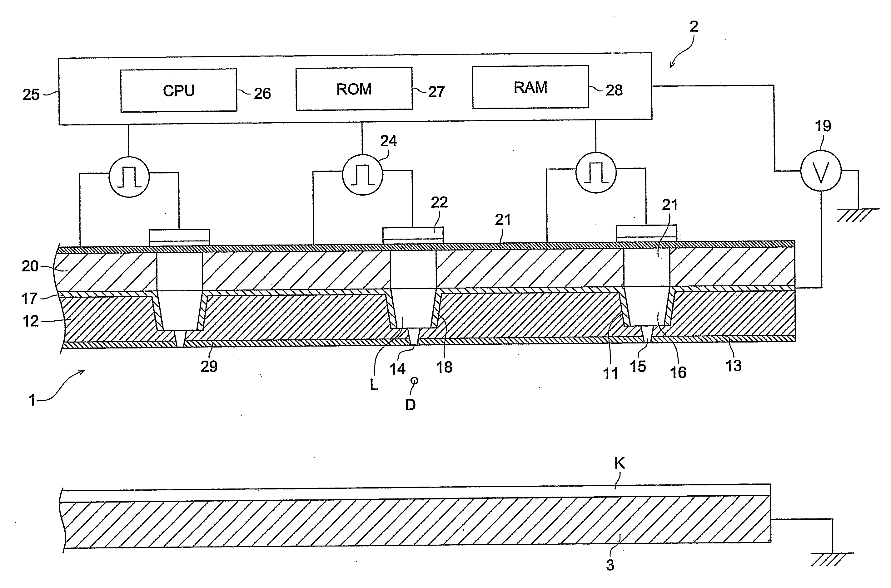
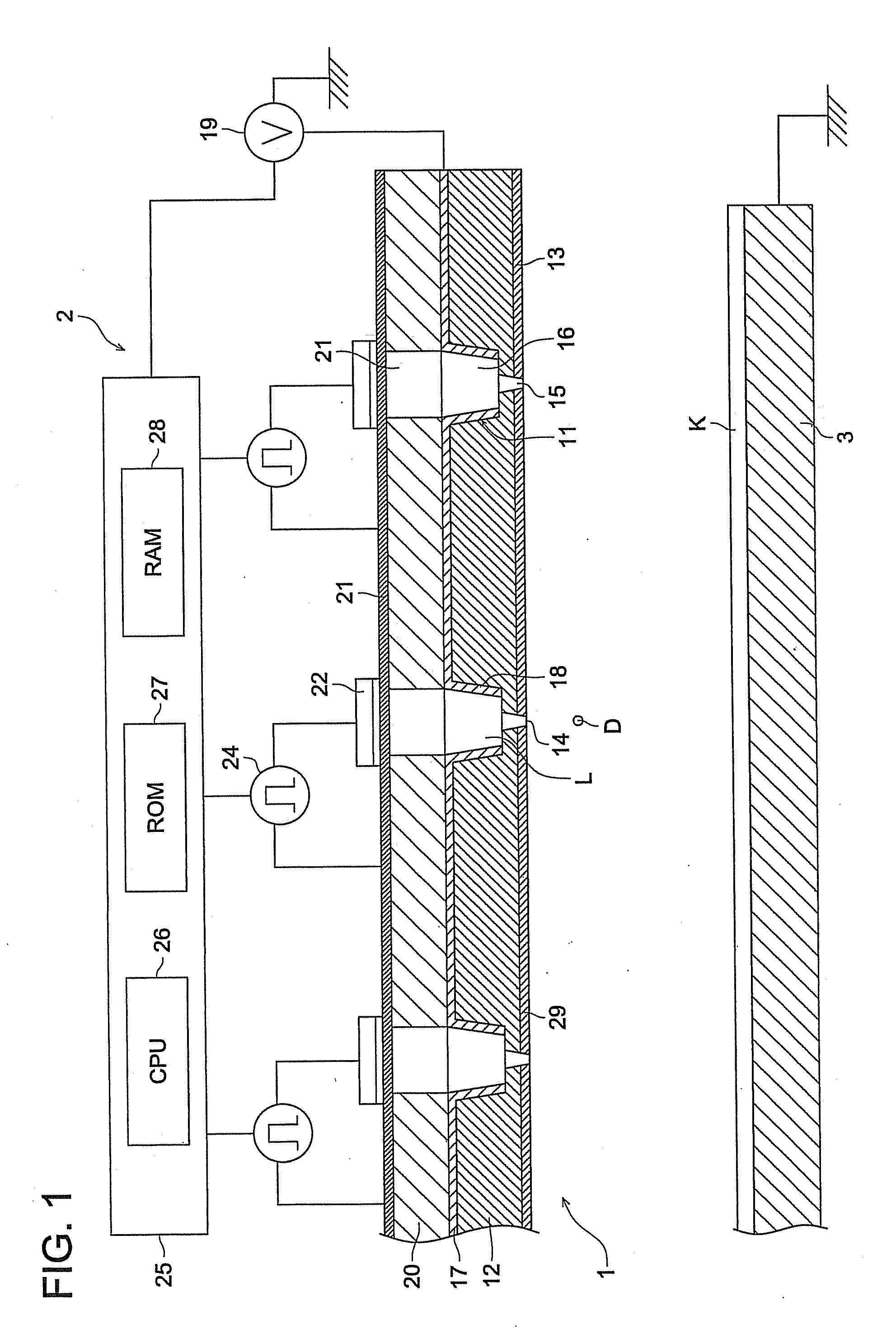
[0127]The nozzle radius, meniscus height, and distance of the inkjet head nozzle surface and substrate K in the present embodiment were changed in several types to verify the state of the liquid ejected from the ejection hole 14 of the nozzle 11.

[0128]The liquid ejection head 2 was manufactured under the same conditions as those for the aforementioned test, and the distance between the inkjet head nozzle surface and the substrate K was set at 10 mm. The voltage VD applied to the piezoelectric element was adjusted while observing the rise of the meniscus.

[0129]Further, the ejection voltage VC was changed and adjusted to the level that permitted ejection, wherein the maximum voltage was set at 2 kV as upper limit. While the ejection voltage VC was changed successively, the state of ejection was observed. Table 1 shows the result under the best ejection conditions. The observation was made under the stroboscopic light using a CCD camera having a 5,000× lens

[0130]The liquid eje...


PUM


Abstract

In a liquid ejection apparatus, having: a liquid ejection head having, a nozzle plate having a nozzle to eject liquid, a cavity to reserve liquid ejected form a ejection hole of the nozzle, a pressure generating device to form a meniscus of the liquid, and a ejecting voltage applying device to apply a ejection voltage to the liquid in the nozzle; a operation control device to control application a drive voltage to drive the pressure generating device and application of the ejection voltage by the ejection voltage applying device; and a counter electrode opposite to the liquid ejection head; wherein in the liquid ejection device in which the liquid is ejected by a static electric attraction force generated between the liquid in the nozzle to which a voltage is applied by the ejection voltage applying device and the counter electrode, and by a pressure generated in the nozzle, the pressure generating device to form the liquid meniscus forms the meniscus having a height of equal to or more than 1.3 times a radius of the nozzle on the ejection hole of the nozzle.

Description

FIELD OF THE INVENTION[0001]The present invention relates to a liquid ejection head and a liquid ejection apparatus, particularly to an electric field concentration type liquid ejection apparatus having a flat nozzle.BACKGROUND OF THE INVENTION[0002]In recent years, there has been a growing demand for formation of a fine pattern formation and ejection of a high-viscosity ink due to the progress of high-definition image quality by inkjet method and expansion in the scope of its application in the industrial field. If the conventional inkjet recording method is used to solve this problem, it is necessary to produce a very fine nozzle and to increase a pressure to eject high-viscosity ink. This requires higher drive voltage and increases cost of the head and the apparatus. Thus, no apparatus that can meet practical use had not been realized.[0003]To meet the aforesaid demand, there is known a technology to eject high-viscosity as well as low-viscosity liquid droplets through a very fin...

Claims


Application Information

Patent Timeline
IPC IPC(8): B41J29/38
CPCB41J2/06
Inventor UENO, NOBUHIRODATE, MASAKAZU
Owner KONICA MINOLTA INC
Why Eureka
Try Eureka