Two-dimensional pilot patterns

a pilot pattern and two-dimensional technology, applied in the field of communication systems with, can solve the problems of pilots being subject to a substantial amount of interference, interference in the ue, and interference becomes particularly critical, and achieves a certain level of orthogonality and better pilot pattern performan

Inactive Publication Date: 2008-05-29
NOKIA TECHNOLOGLES OY
View PDF7 Cites 26 Cited by
  • Summary
  • Abstract
  • Description
  • Claims
  • Application Information

AI Technical Summary

Benefits of technology

[0013]The present invention is to propose a solution for or a reduction of one or more of the problems of the prior art. The present invention is consequently to devise a method that enables flexible planning of pilot patterns with regard to occupied area of the T-F-grid, that enables better pilot pattern performance, in terms of mitigation of hits under bad transmission channel conditions or under interference from other users, that enables generation of a multitude of patterns, that also is suitable for MIMO-systems, and finally all of this while ensuring a certain level of orthogonality between pilot patterns, i.e. ensuring a predictable maximum amount of mutual hits between patterns, both under synchronous and asynchronous operation.

Problems solved by technology

If all the transmitted pilot patterns are the same, they will interfere in the UE, especially if the UE is close to the cell edge.
As pilot signals in general have higher power than data signals, this interference becomes particularly critical.
The potential problem for channel estimation with this approach is that the sampling interval in frequency domain depends on the slope, so the different base stations will have different minimum sampling intervals.
One problem with the prior art above is that when a certain portion of the communication channel is bad, or when experiencing interference from a neighbouring base station, the pilots may be subject to a substantial amount of interference.
This can severely degrade the performance of such a system.
Another problem with prior art pilot patterns arises when pilot patterns are used with MIMO (Multiple Input, Multiple Output)-systems, which are systems that use multiple transmit and receive antennas.
Because the amount of patterns available according to prior art is limited, they soon could get exhausted when used with MIMO.
A further problem with the prior art is that pilot patterns are defined over the whole frequency spectrum.
Yet another problem is to make sure that pilot patterns are as orthogonal as possible, also when users are not synchronised, i.e. under arbitrary time shift.

Method used


Image

  • Two-dimensional pilot patterns
  • Two-dimensional pilot patterns
  • Two-dimensional pilot patterns

Examples


Embodiment Construction

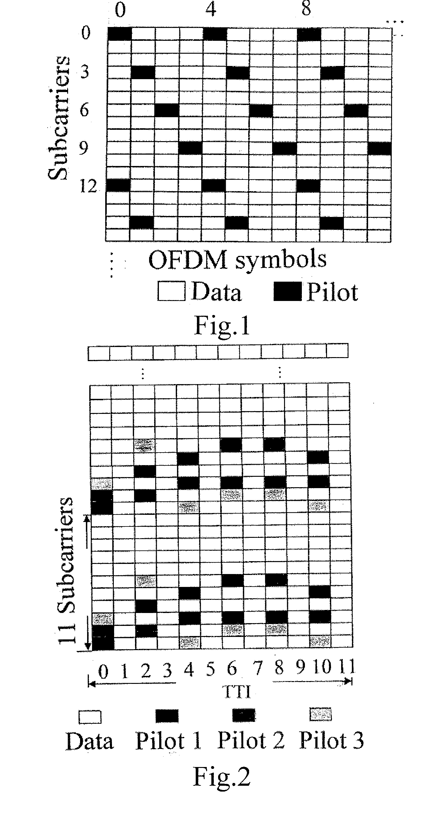
[0026]To familiarise the concept of pilot patterns, FIG. 1 shows a T-F grid (time-frequency grid) including frequency and time axes, forming a communication channel. In this grid, an exemplary pilot pattern, for channel estimation, is depicted. The pilot pattern includes tones that are modulated on to certain carriers at certain time instances, these time / frequency slots with pilots are illustrated with black squares in the grid. In this example the pilot pattern can be said to have a slope in the grid.

[0027]According to the invention, a general design method for two-dimensional pilot patterns for channel estimation is specified on the basis of the repetition of a generic pilot pattern in one of the two dimensions. A generic pilot pattern covers completely one dimension and covers partially the second dimension, within a segment of the second dimension where the propagation channel is considered to have a constant value. This can be seen from FIG. 2, which shows three different pilo...


PUM


Abstract

The present invention relates to a method for generating, in a multiple access communication system, two-dimensional pilot signal patterns for propagation channel estimation in time and frequency, with equidistant sampling. The method includes the steps of: generating a generic pilot pattern that covers completely a first dimension and covers partially a second dimension, within a segment of the second dimension where the propagation channel is considered to have a constant value, and performing periodical duplication of the generic pilot pattern along the second dimension, where the duplication interval of the generic pilot pattern is equal to the required sampling interval in the second dimension. The invention also relates to a transmitter and a receiver of a multiple access communication system, such as a multiple access communication system and a radio multiple access communication system.

Description

FIELD OF THE INVENTION[0001]The present invention relates to communications systems with multiple (sub-) carriers. More exactly it concerns a method according to the preamble of claim 1. Further, it concerns a transmitter, a receiver, a multiple access communication system and a radio multiple access communication system according to claims 10, 11, 12, 13, respectively.BACKGROUND OF THE INVENTION[0002]Multiple access communications systems are distinguished by the capability of efficient sharing of the limited bandwidth between the multiple users. The mutual interference between the signals of multiple users can be controlled or completely eliminated by different mechanisms, such as time-division multiple access (TDMA), frequency-division multiple access (FDMA), orthogonal frequency-division multiple access (OFDMA), code-division multiple access (CDMA) and multi-carrier CDMA (MC-CDMA).[0003]Besides the data signals, there are a number of other signals transmitted from each user that...

Claims


Application Information

Patent Timeline
Patent Type & Authority Applications(United States)
IPC IPC(8): H04Q7/00H04L27/28
CPCH04L5/0023H04L25/0226H04L25/0204H04L5/0048
Inventor POPOVIC, BRANISLAV
Owner NOKIA TECHNOLOGLES OY
Why Eureka
Try Eureka