Microphone module and mounting structure adapted to portable electronic device

Inactive Publication Date: 2008-05-29
YAMAHA CORP
View PDF5 Cites 37 Cited by
  • Summary
  • Abstract
  • Description
  • Claims
  • Application Information

AI Technical Summary

Benefits of technology

[0011]It is an object of the present invention to provide a microphone module and its mounting structure, by which the degree of

Problems solved by technology

As described above, the conventionally-known microphone module is troublesome because it is necessary to change the positions of the external connection terminal and sound hole within the exterior surface in response to the position of the mount portion of the circuit board, which is positioned

Method used


Image

  • Microphone module and mounting structure adapted to portable electronic device
  • Microphone module and mounting structure adapted to portable electronic device
  • Microphone module and mounting structure adapted to portable electronic device

Examples


first embodiment

1. First Embodiment

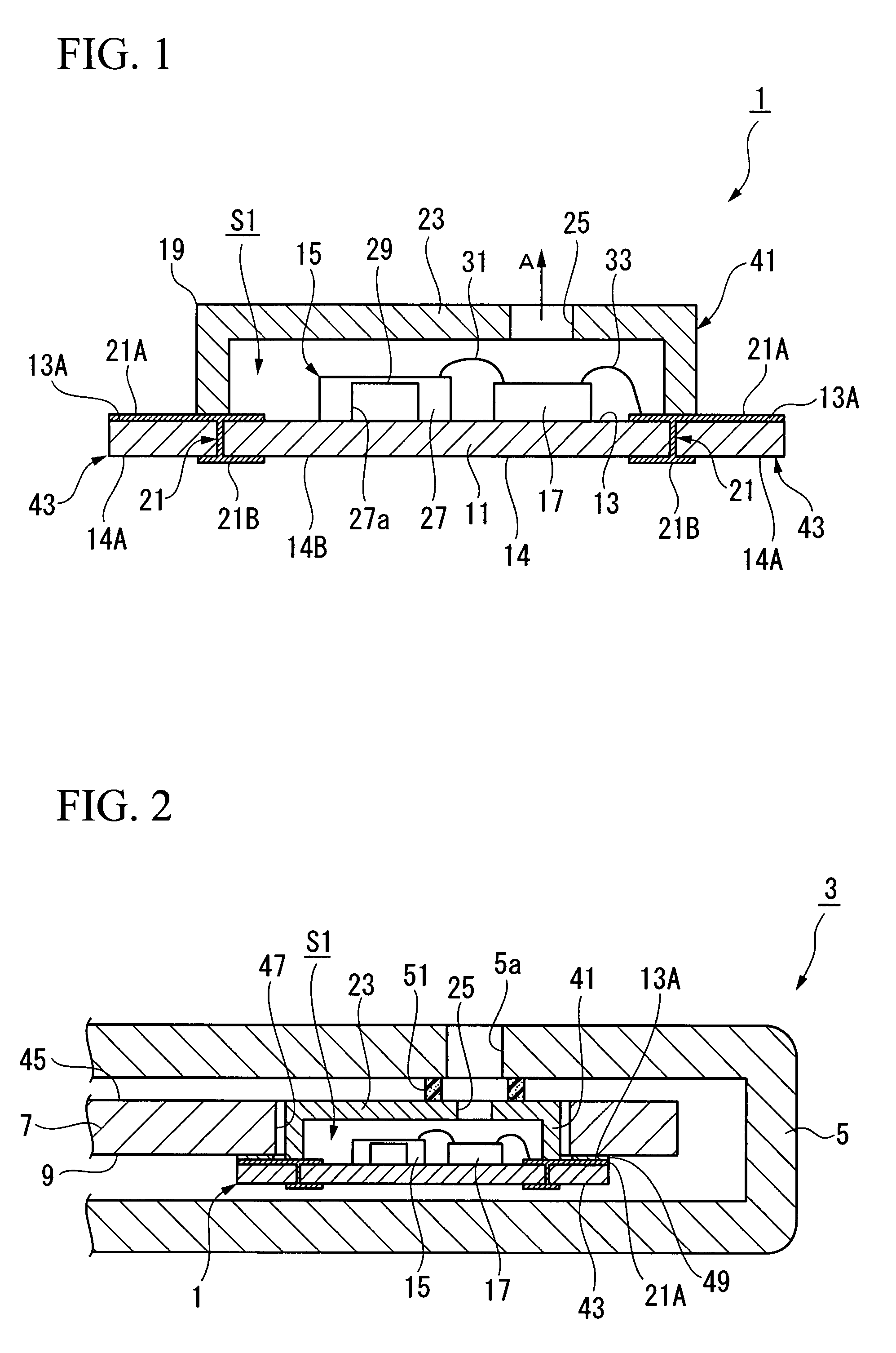
[0037]A microphone module 1 according to a first embodiment of the present invention will be described with reference to FIGS. 1 to 3.

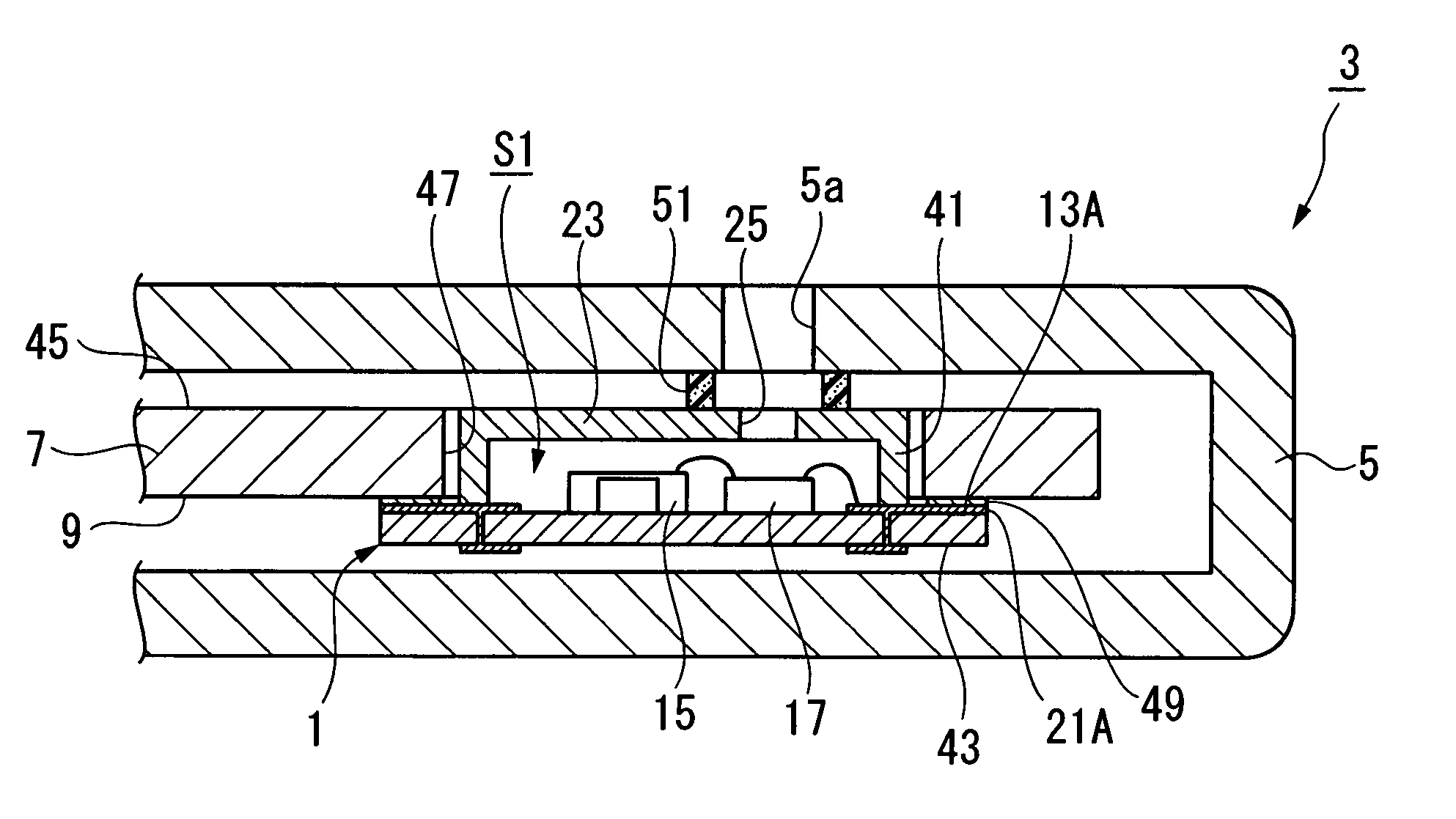
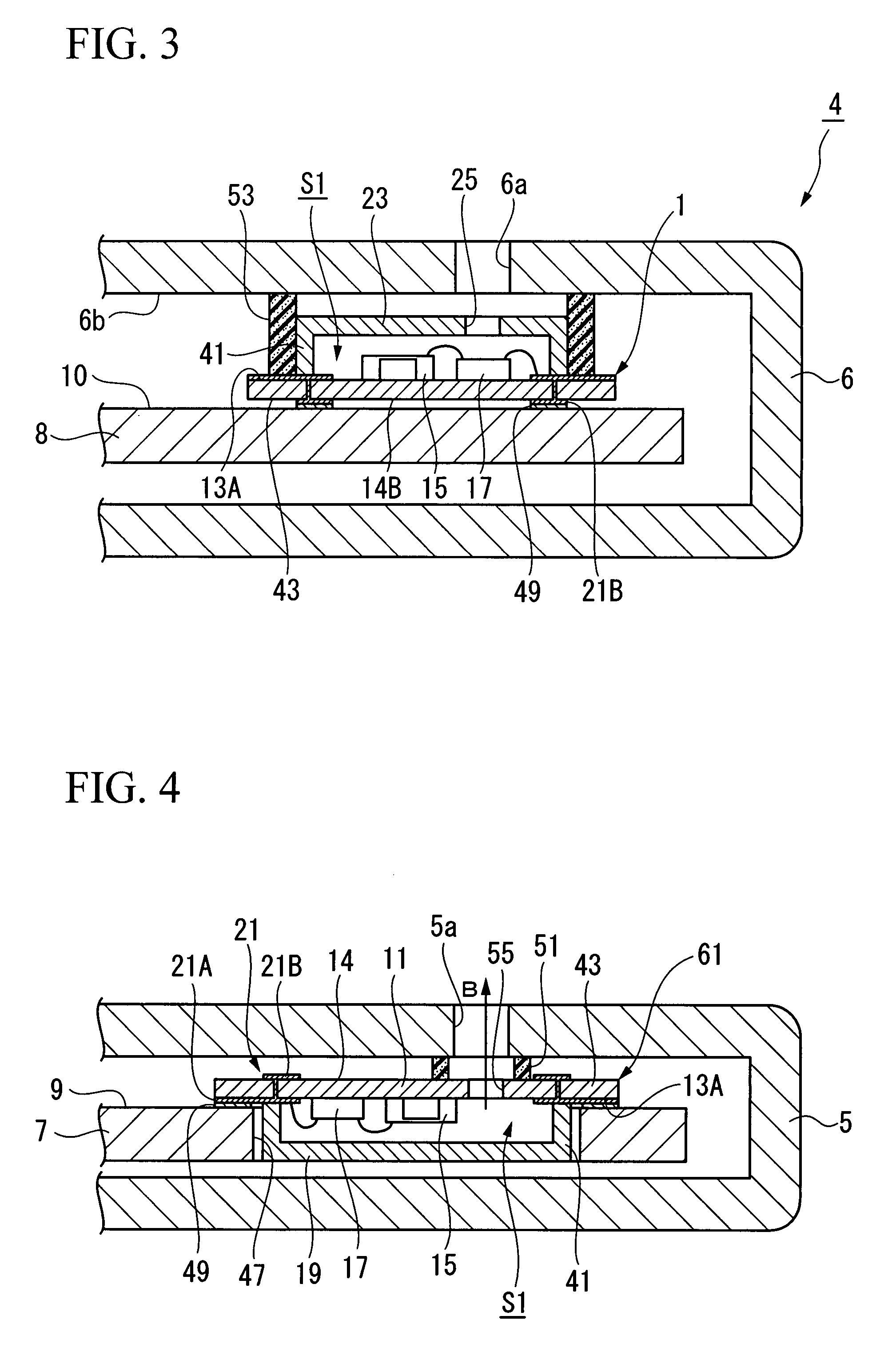
[0038]As shown in FIGS. 2 and 3, the microphone module 1 is designed to suit housings 5 and 6 of portable electronic devices (e.g., portable telephones) respectively. Specifically, the microphone module 1 is designed in a shape, which can be mounted on mount portions 9 and 10 of circuit boards 7 and 8 incorporated in the housings 5 and 6 of the portable electronic devices 3 and 4 respectively.

[0039]As shown in FIG. 1, the microphone module 1 includes a substrate 11 having a rectangular shape in plan view, a microphone chip 15 and a control circuit chip 17 fixed onto a surface 13 of the substrate 11, and a cover member 19, which covers a part of the surface 13 of the substrate 11 including the microphone chip 15 and the control circuit chip 17 so as to form a hollow cavity S1 together with the substrate 11. Herein, peripheral portion...

second embodiment

2. Second Embodiment

[0077]Next, a microphone module 101 according to a second embodiment of the present invention will be described in detail with reference to FIGS. 6 to 9, wherein parts identical to those of the microphone module 1 as well as parts identical to those of the portable electronic devices 3 and 4 are designated by the same reference numerals; hence, the descriptions thereof will be omitted as necessary.

[0078]As shown in FIG. 6, the microphone module 101 is constituted of a main body 103 and a support 105 for mounting and supporting the main body 103.

[0079]The main body 103 of the microphone module 101 is constituted of a substrate 107 having a rectangular shape in plan view, the microphone chip 15 and the control circuit chip 17 both fixed onto a surface 107a of the substrate 107, and a cover member 109 that entirely covers the surface 107a of the substrate 107 including the microphone chip 15 and the control circuit chip 17 so as to form a hollow cavity S3 with the s...


PUM


Abstract

A microphone module is mounted on a mount portion of a circuit board incorporated in a portable electronic device, wherein it includes a housing having a hollow cavity and a sound hole for communicating the hollow cavity with the exterior, a microphone chip for detecting sound in the hollow cavity, a plurality of external connection terminals electrically connected to the microphone chip, and a plurality of extended portions that are horizontally extended from the housing in a direction perpendicular to the opening direction of the sound hole. The external connection terminals are formed on the surfaces of the extended portions; and the housing partially projects from the surfaces of the extended portions.

Description

BACKGROUND OF THE INVENTION[0001]1. Field of the Invention[0002]The present invention relates to microphone modules for receiving and detecting sounds. The present invention also relates to mounting structures for installing microphone modules in portable electronic devices.[0003]This application claims priority on Japanese Patent Application No. 2006-244268, the content of which is incorporated herein by reference.[0004]2. Description of the Related Art[0005]Conventionally-known portable electronic devices such as portable telephones and cellular phones are equipped with microphone modules for receiving and detecting sounds. For example, U.S. Patent Application Publication No. 2006 / 0116180 teaches an acoustic transducer module, i.e., a miniature silicon condenser microphone module adapted to micro-electromechanical systems (MEMS). This type of the microphone module includes an external connection terminal and a sound hole to enter sound, both of which are formed on the exterior sur...

Claims


Application Information

Patent Timeline
IPC IPC(8): H04R11/04
CPCH04M1/03H04R1/06H04R1/08H04R2499/11H05K2201/10083H05K1/141H05K2201/049H05K2201/09072H05K1/0284H04R1/02
Inventor KATO, HIROKAZUSUZUKI, TOSHIHISA
Owner YAMAHA CORP
Why Eureka
Try Eureka