Porous burner as well as a method for operating a porous burner
- Summary
- Abstract
- Description
- Claims
- Application Information
AI Technical Summary
Benefits of technology
Problems solved by technology
Method used
Image
Examples
Embodiment Construction
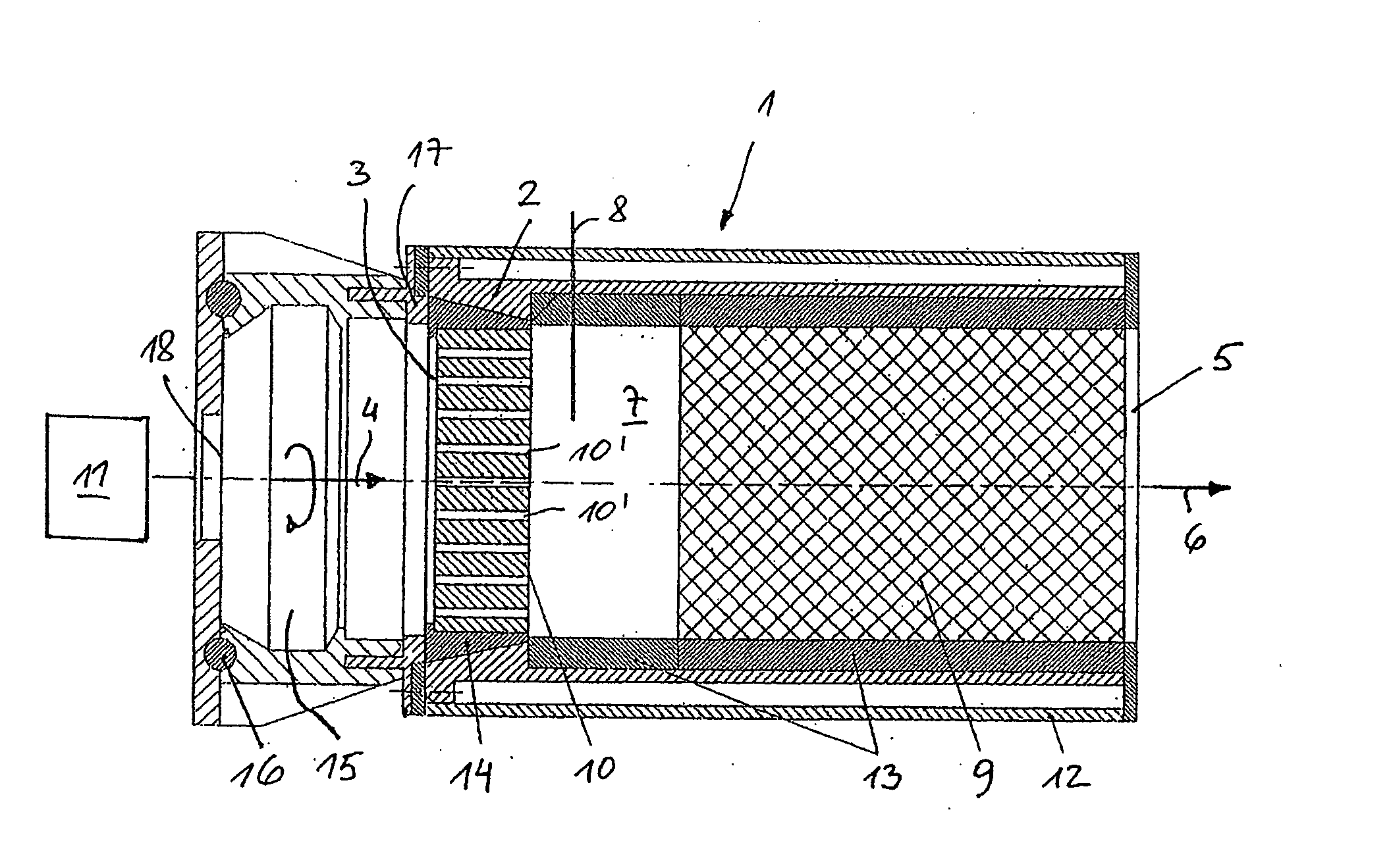
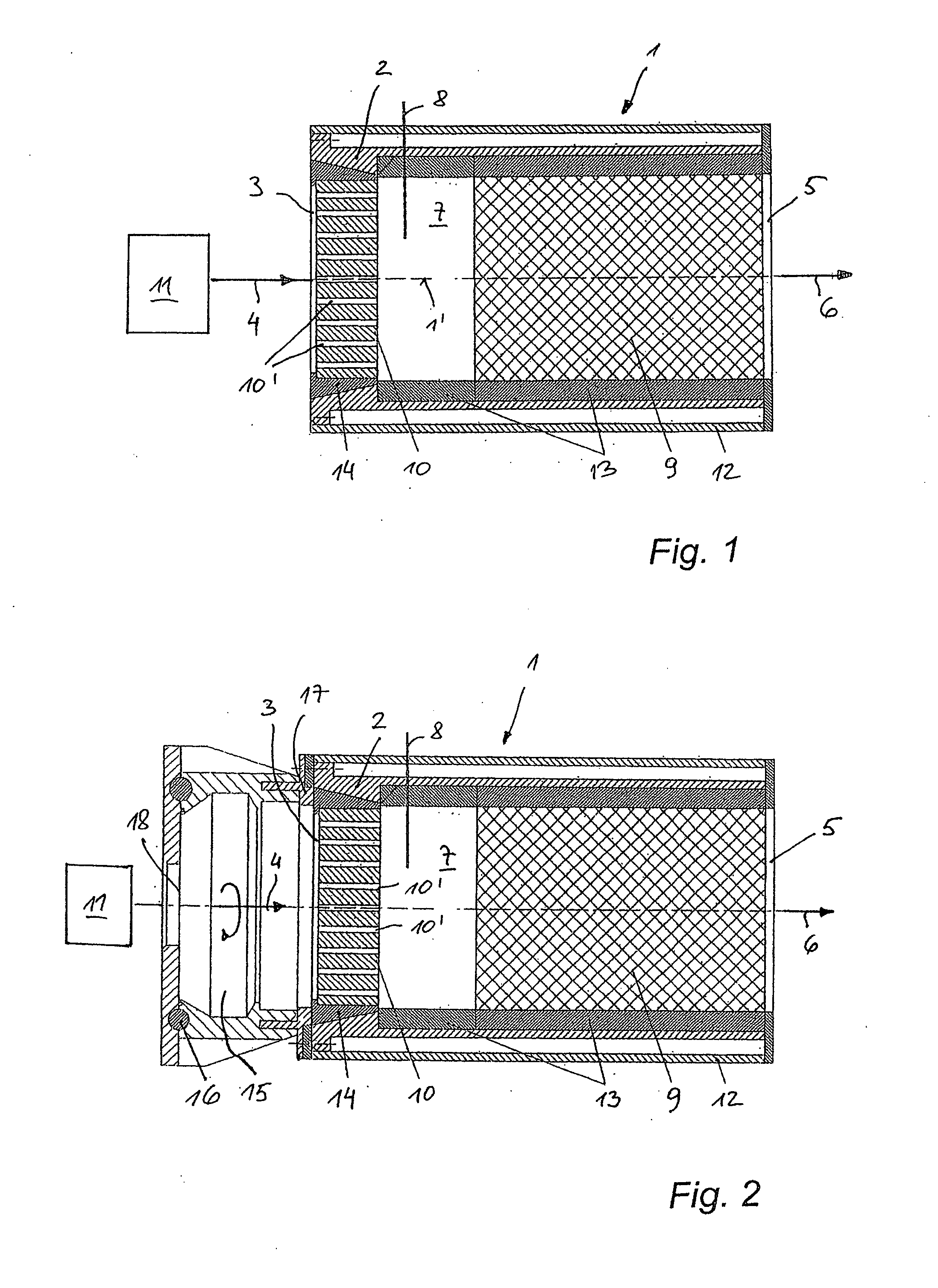
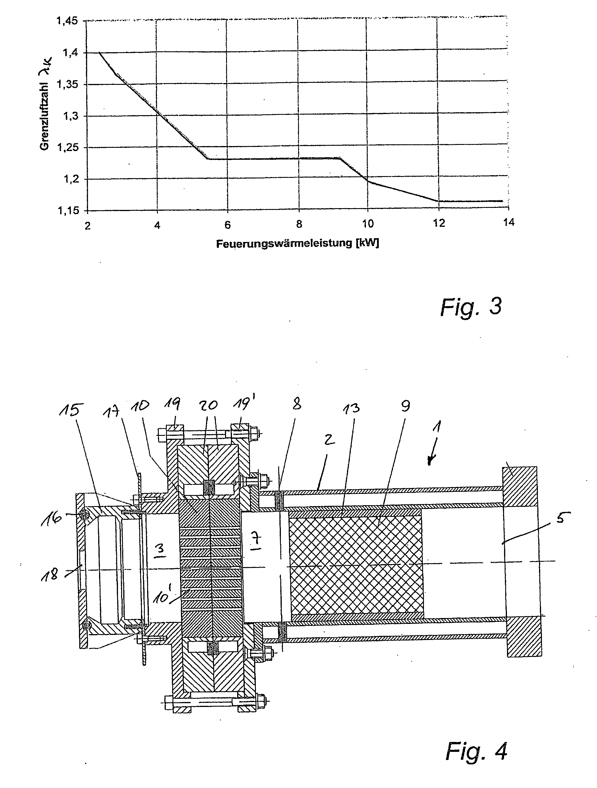
[0036]The porous burner shown in FIG. 1 (for instance, a gas burner) has a housing 2 with an inlet 3 for a fuel-air mixture 4 and an outlet 5 for the exhaust gas mixture 6 generated in the burner, where in flow direction of the process gases there is provided in the housing 2 an ignition space 7 with an ignition device 8 followed by a ceramic porous medium 9. The ignition space 7 is bounded on the inlet side by a stabilizing element 10, a perforated ceramic plate, which reduces the inlet cross-section and redirects the flow of the fuel-air mixture 4 in such a way that it is perpendicular to the inlet cross-section of the porous medium 9. In the example shown, which is a cylindrical porous burner, the fuel-air mixture is directed parallel to the axis 1′ of the porous burner 1. The porous burner 1 furthermore is provided with a device 11 for controlling the mass flow of the fuel-air mixture 4, for instance a pressure blower in front of the burner or a suction fan behind the burner. Pr...
PUM
 Abstract
Description
Claims
Application Information
 - R&D
- Intellectual Property
- Life Sciences
- Materials
- Tech Scout
- Unparalleled Data Quality
- Higher Quality Content
- 60% Fewer Hallucinations
Browse by: Latest US Patents, China's latest patents, Technical Efficacy Thesaurus, Application Domain, Technology Topic, Popular Technical Reports.
© 2025 PatSnap. All rights reserved.Legal|Privacy policy|Modern Slavery Act Transparency Statement|Sitemap|About US| Contact US: help@patsnap.com


