
Indwelling urinary catheter with enlarged sealing surface

a catheter and sealing surface technology, applied in the field of urinary catheters, can solve the problems of traumatic irritation in long-term catheterization, and achieve the effect of increasing the sealing effect of the balloon

Inactive Publication Date: 2008-05-29
KIMBERLY-CLARK WORLDWIDE INC
View PDF11 Cites 13 Cited by
  • Summary
  • Abstract
  • Description
  • Claims
  • Application Information

AI Technical Summary

Benefits of technology

[0013]As such in one aspect, the present invention serves to avoid the above-mentioned disadvantages associated with the catheters described above and to devise an indwelling urinary catheter capable of simple manufacture from a standpoint of production engineering. Such a catheter should be designed to expand the existing art by providing a special embodiment of a urinary catheter, specifically designed for the requirements of longterm catheterization and the prevention of complications associated with longterm placement of a balloon-equipped catheter in the urinary bladder. Use of the device is anticipated to reduce the incidence of pressure induced ulcers due to the continuous mechanical irritation of bladder tissue typically associated with prior art high pressured balloons, wherein a stiff, inflexible, fully distended balloon structure is made to rest within the trigonum-shaped outlet-portion of the urinary bladder, causing typical force-induced trauma at the resting area between balloon and bladder.
[0014]Unlike in the prior art balloons, the balloon of the present device is preformed to a defined fully inflated volume prior to affixing it to the catheter shaft. Once attached to the shaft, it may be placed in a first condition, that is, a resting volume or base state, characterized in that the balloon is deflated and collapsed into a film-like structure. The collapsed film-like structure does not meaningfully increase the outer diameter of the shaft and as such the shaft and collapsed balloon are insertable through the urethra and removable without increasing urethral irritation or trauma.
[0015]Once the catheter is positioned, the balloon is inflated to a working volume which is less than that of its fully inflated volume. At this working volume, the balloon would better conform to the shape of the bladder and more specifically the trigonum vesicae. Due to the balloon being inflated to a volume less than its capacity, the balloon foil itself could be made to contact more of the bladder wall. This would increase the sealing properties of the catheter further minimizing leakage of urine past the balloon as well as the ascension of bacteria from the external environment, up through the urethra, and into the bladder. Moreover the balloon may be coated so as to have an antimicrobial effect as well as to minimize the encrustation of urine based compounds on the outside as well as the inside surfaces of the balloon.
[0016]One such catheter described in accordance with the present invention would be simple to manufacture in terms of production engineering and would eliminate the need for cost-intensive manufacturing steps in comparison to conventional catheter types, such as, above all, latex catheters which are manufactured using a dipping method. Additionally, the described balloon further overcomes the problem of changing material mechanics, specifically, the stiffening of the material after prolonged inflation which is associated with conventional materials often causing traumatic irritation in long-term catheterization.
[0018]In another embodiment of the present invention, a method is disclosed. The method includes the steps of introducing a flexible catheter having a balloon through the urethra and into the bladder. Once placed the user may inflate the balloon in a range of between about 50 to about 80 percent of its pre-shaped or fully inflated volume. The sealing effect of the balloon may be increased by subjecting the catheter to a tractive force while it is intravesically in situ. In embodiments similar to tis, the balloon may contact the internal urinary bladder structures over a range from at least about 30 percent of the balloon surface area to at least about 60 percent of the balloon surface area.

Problems solved by technology

Additionally, the described balloon further overcomes the problem of changing material mechanics, specifically, the stiffening of the material after prolonged inflation which is associated with conventional materials often causing traumatic irritation in long-term catheterization.

Method used


Image

  • Indwelling urinary catheter with enlarged sealing surface
  • Indwelling urinary catheter with enlarged sealing surface
  • Indwelling urinary catheter with enlarged sealing surface

Examples


Embodiment Construction

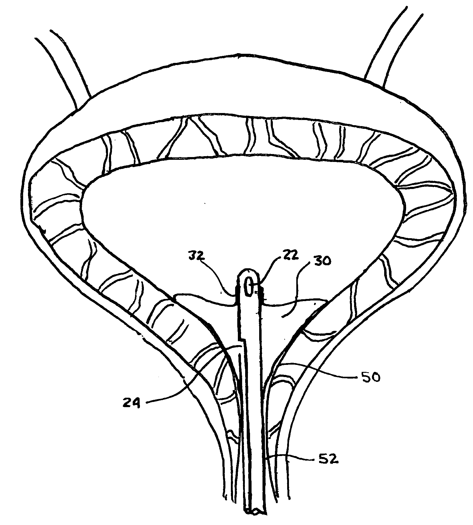
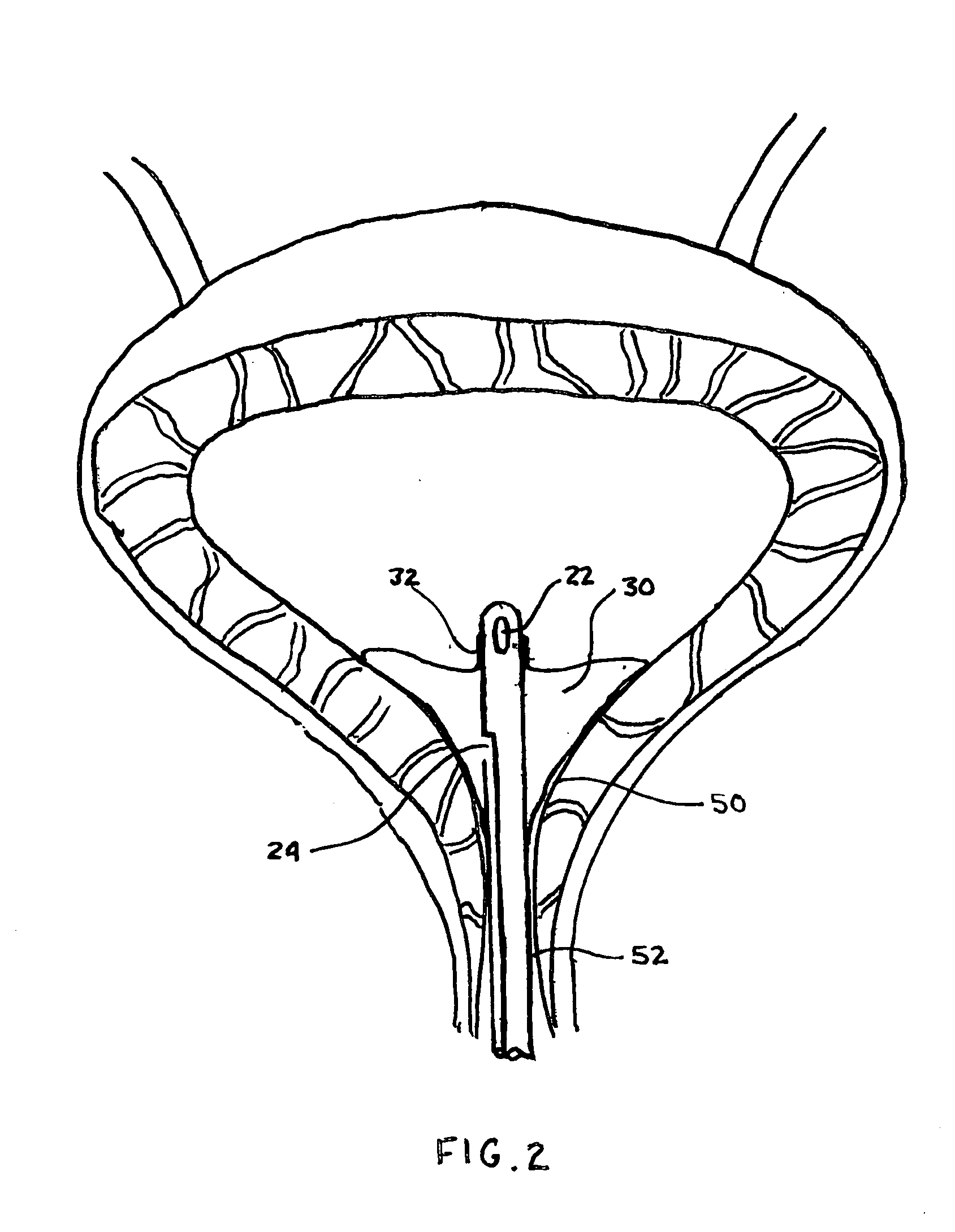
[0022]In response to the foregoing challenges that have been experienced by those of skill in the art, the present invention is directed toward an improved indwelling urinary catheter that conforms more readily to the trigonum vesicae structure of the bladder thus better sealing the internal urethral orifice and reducing the incidence of ulceration of the bladder structures and infection of the same from transurethral migration of bacterium.

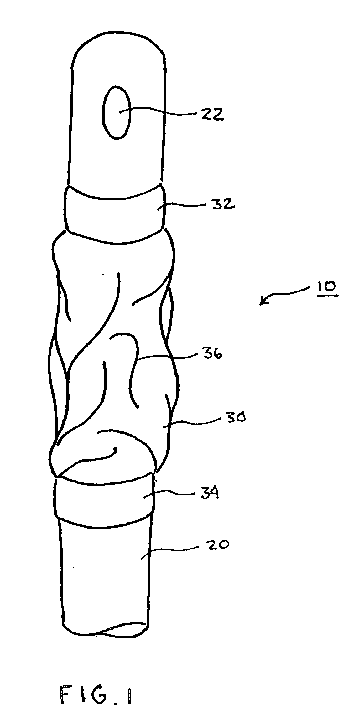
[0023]FIG. 1 shows the distal end of an indwelling urinary catheter 10 in a lateral illustrative view. The catheter 10 is provided with a shaft 20 and a balloon 30 affixed to the shaft 20. Proximal to the distal end of the shaft 20 is an orifice 22 which serves to drain urine or other fluids through the interior of the catheter 10. The balloon 30 is shown in a base-state, i.e. at rest and fully collapsed. Bands 32 and 34 are formed by the ends of the balloon 30 and serve as fluid tight bonds between the shaft 20 and the balloon 30. The bonding of...


PUM


Abstract

An indwelling urinary catheter for transurethral introduction into a urinary bladder is shown and described herein. The catheter includes a flexible catheter shaft having a wall, a filling channel is integrated into the wall, and a thin foil balloon element having a film-like structure. The balloon element when positioned in the bladder is adapted to contact internal urinary bladder structures over at least about 30 percent of a balloon element surface area. The seal is greater than seals of equivalent balloon structures.

Description

BACKGROUND OF THE INVENTION[0001]The present invention is directed to a urinary catheter for transurethral introduction into the urinary bladder through the urethra. More particularly, the present invention is directed to an indwelling urinary catheter that conforms more readily to the trigonum vesicae structure of the bladder thus better sealing the internal urethral orifice and reducing the incidence of ulceration of the bladder structures.[0002]When providing health care, the use of a urinary catheter is often required. The indwelling urinary catheter most often in use today is the Foley catheter. A Foley catheter is composed of a flexible catheter shaft having a distal end which is placed in the patient's bladder. A fluid-refillable balloon element is fastened to the shaft. The catheter shaft has a filling channel, which leads into the balloon interior via an opening in the catheter wall. The main purpose of the balloon element is to securely mechanically anchor the catheter in ...

Claims


Application Information

Patent Timeline
Patent Type & Authority Applications(United States)
IPC IPC(8): A61M27/00
CPCA61M25/04A61M25/0017
Inventor GOBEL, FRED
Owner KIMBERLY-CLARK WORLDWIDE INC
Learn More