Supercharge Your Innovation With Domain-Expert AI Agents!

Turbo decoder and turbo decoding method

a decoding method and turbo technology, applied in the direction of coding, redundant data error correction, instruments, etc., can solve the problems of access conflict, inability to avoid access conflict at the time of writing and reading, and difficulty in coping with the above problems

Inactive Publication Date: 2008-05-29
FUJITSU LTD
View PDF7 Cites 12 Cited by
  • Summary
  • Abstract
  • Description
  • Claims
  • Application Information

AI Technical Summary

Benefits of technology

[0038]The present invention is devised in view of the above problems, and its object is to avoid conflict of an access to a memory to be used in an interleaving process and a deinterleaving process to be executed at the turbo decoding step in a turbo decoder for operating a plurality of element decoders in parallel.
[0039]It is preferably an object of the present invention to avoid the memory access conflict without increasing the capacity of a memory to be required for the interleaving process and the deinterleaving process to be executed at the turbo decoding step.
[0055]According to the present invention, after the element decoded result in each of the element decoders is written with the addresses belonging to the different rows in the matrix-patterned memory spaces where writing and reading are possible in parallel in the different rows being specified as the writing start addresses, the element decoded results are read with the addresses belonging to the different rows being specified as the reading start addresses. For this reason, at least the following effect and advantage can be obtained.
[0056]Namely, in the turbo decoder which operates a plurality of element decoders in parallel in order to carry out high-speed turbo decoding, memory access conflict can be avoided without increasing the capacity of memory required for the interleaving process and the deinterleaving process to be executed at the turbo decoding step and without increasing a memory access clock and a processing delay time.

Problems solved by technology

On the contrary, even if the RAM 30 is divided into banks according to the reading, the access becomes random at the time of writing, and thus access conflict possibly occurs.
For this reason, the access conflict at the time of writing and reading cannot be avoided in simple bank division.
Any of these, however, is not preferable because a circuit size, or processing time and current consumption, etc. are affected.
Further, in the case where the number of the element decoders to be arranged in parallel is increased in order to realize a higher-speed process, it is very difficult to cope with the above problems by these methods.

Method used


Image

  • Turbo decoder and turbo decoding method
  • Turbo decoder and turbo decoding method
  • Turbo decoder and turbo decoding method

Examples


first embodiment

[A] First Embodiment

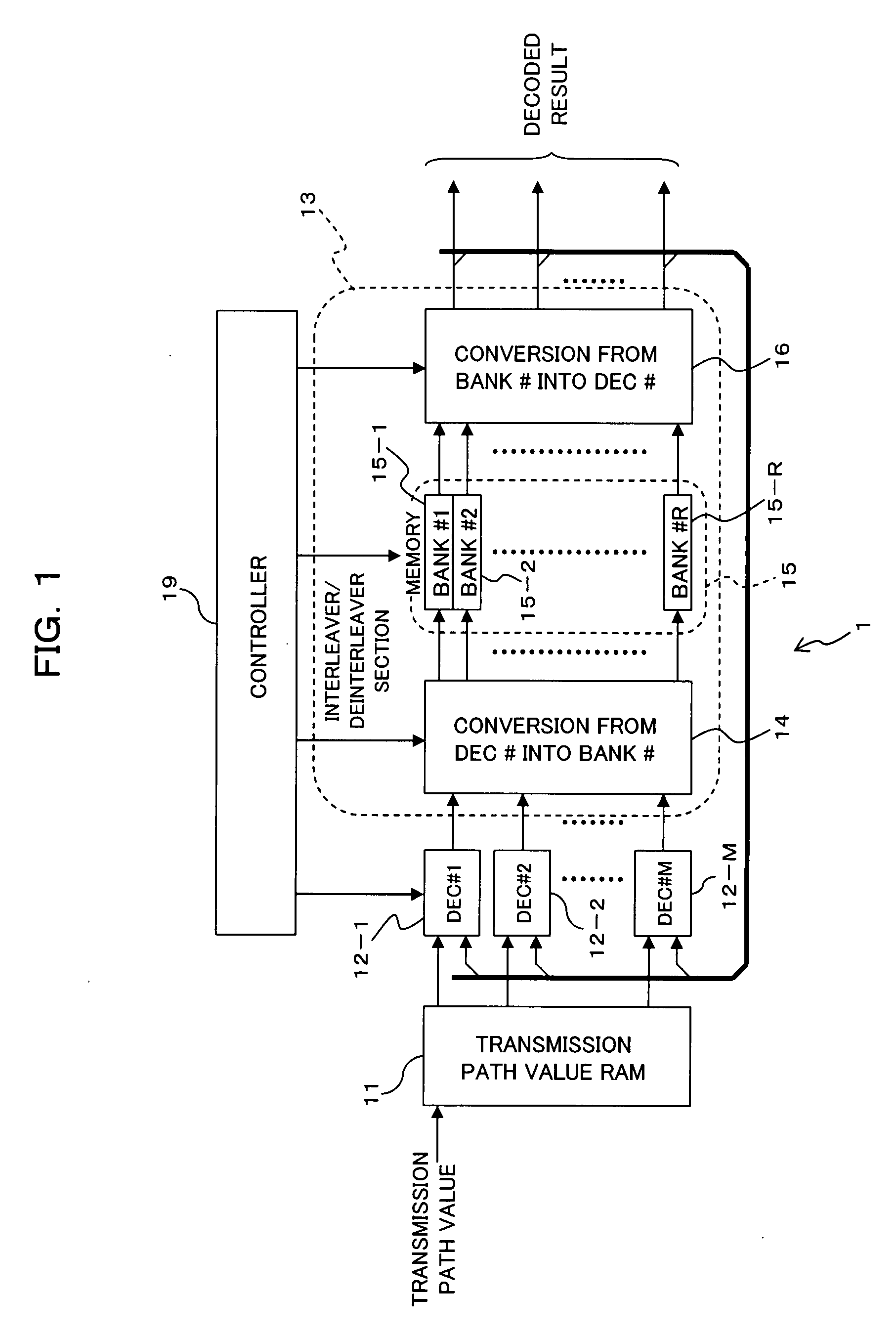
[0075]FIG. 1 is a block diagram illustrating a main structure of a turbo decoder according to a first embodiment of the present invention, and the turbo decoder 1 shown in FIG. 1 is applied to a receiver composing a communication system shown in FIG. 10, for example. The turbo decoder 1 includes a transmission path value memory (RAM) 11, the M pieces (M is an integer of 2 or larger) of elements decoders (DEC#1 to DEC#M) 12-1 to 12-M, and an interleaver / deinterleaver section 13. The interleaver / deinterleaver section 13 includes parallel number (DEC#→bank#) converting section (connection switching section) 14, a memory section 15, a parallel number (bank#→DEC#) converting section (connection switching section) 16, and a controller (memory controller) 19. A structure of the receiver (turbo encoder) is the same as or similar to a structure shown in FIG. 11, for example.

[0076]The transmission path value RAM 11 stores received signals (signals to be decoded) ya, yb, an...

second embodiment

[B] Second Embodiment

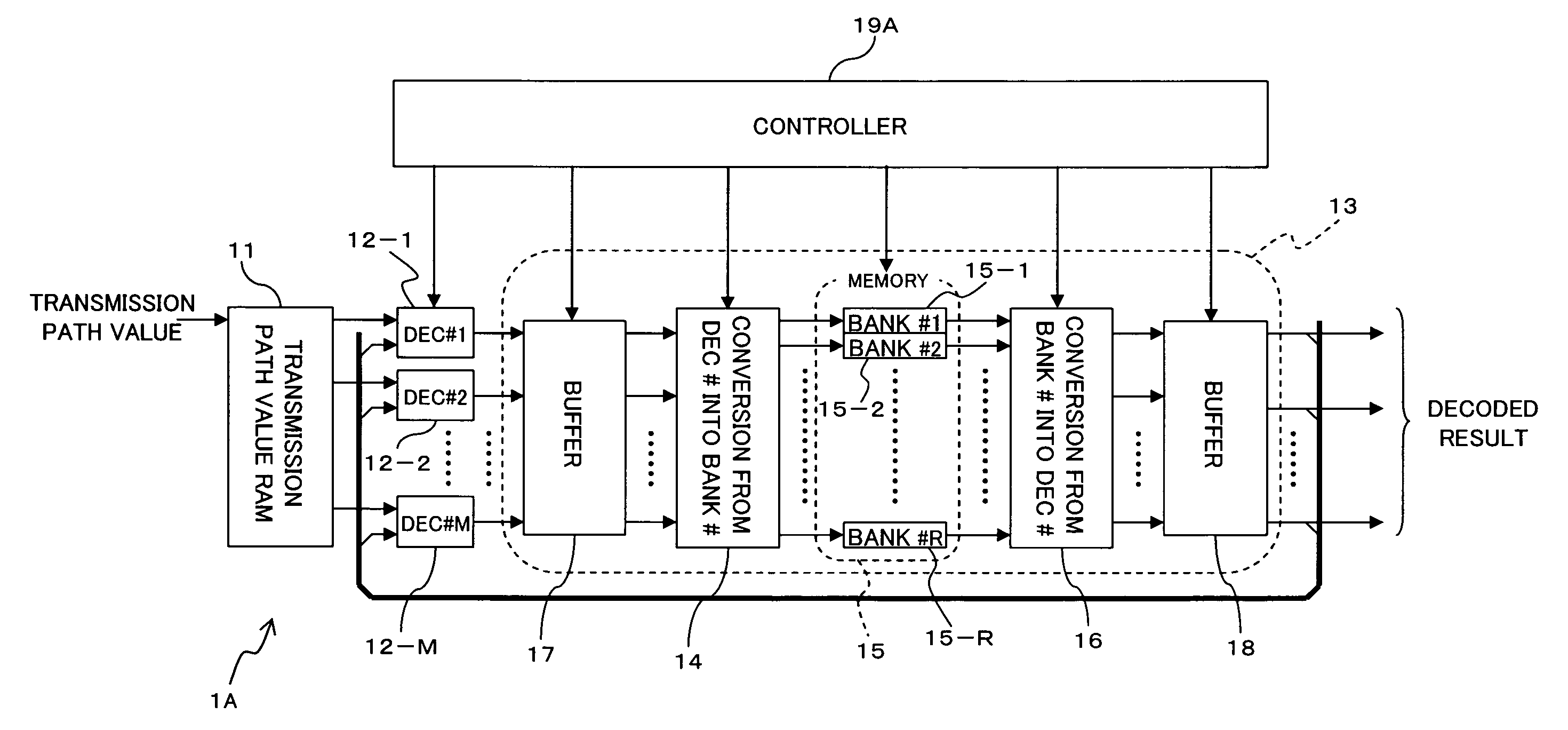
[0099]FIG. 4 is a block diagram illustrating a main structure of a turbo decoder according to a second embodiment of the present invention. The turbo decoder 1A shown in FIG. 4 is different from the turbo decoder 1 shown in FIG. 1 in that a buffer section 17 is provided onto an input side of the connection switching section 14 and a buffer section 18 is provided onto an output side of the connection switching section 16 in the interleaver / deinterleaver section 13, and a controller (memory controller) 19A is provided instead of the controller 19. The other components having the same reference symbols have the same or similar functions as / to those of the above-mentioned components unless otherwise noted.

[0100]The buffer sections 17 and 18 can adjust (delay) output timings (phases) of the M-parallel input data (element decoded results) individually under the control of the controller 19A. Fucusing on the buffer section 18, as shown in (6) of FIG. 5, for example, th...

first modification

(B1) First Modification

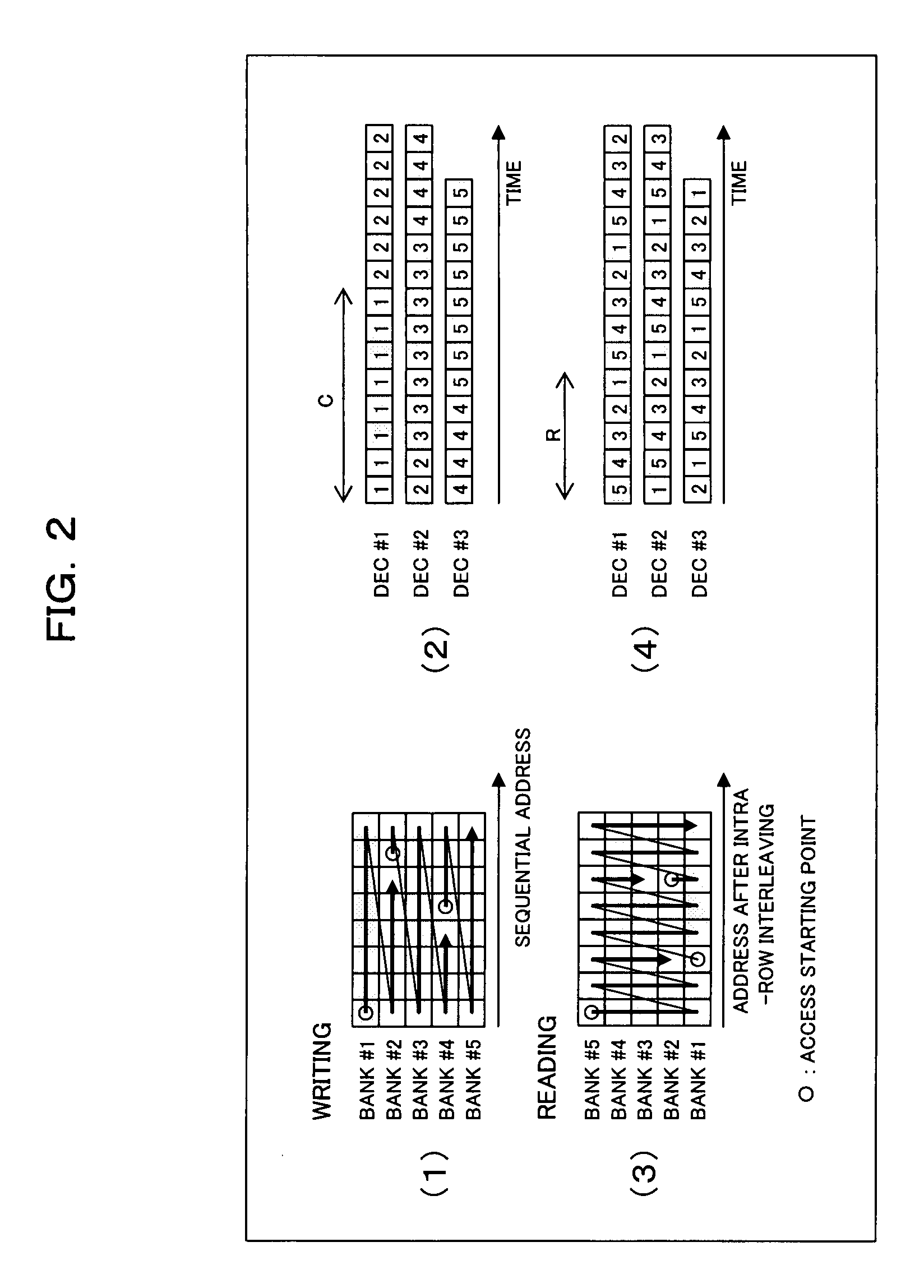
[0109]In the second embodiment, when M pieces of the parallel element decoders 12-i do not have to be operated simultaneously, as shown in FIG. 6, the element decoders 12-i are operated by the controller (memory controller) 19B with the decoding start timings being shifted according to the phase shift. As a result, the phase shift between M pieces of the parallel element decoded results does not have to be absorbed by the buffer sections 17 and 18 (see (1) to (4) of FIG. 7).

[0110]As shown in FIG. 6, therefore, the turbo decoder 1B of this example, which has the structure of the turbo decoder 1 in the first embodiment as a basic structure, can avoid the access conflict in the case where the data about the decoding start points of the respective element decoders 12-i are present in one bank 15-j.


PUM


Abstract

A turbo decoder includes a plurality of element decoders, a memory section that stores element decoded results in matrix-patterned memory spaces, and a memory controller that writes the element decoded result of each of the element decoders in a row or column direction in the matrix-patterned memory spaces with addresses belonging to different rows being specified as writing start addresses, and reads them in the column or row direction with the addresses belonging to different rows being specified as reading start address. As a result, conflict of accesses to the memory required for an interleaving process and a deinterleaving process to be executed at the turbo decoding step can be avoided.

Description

CROSS REFERENCE TO RELATED APPLICATION(S)[0001]This application is based on and hereby claims priority to Japanese Application No. 2006-318331 filed on Nov. 27, 2006 in Japan, the contents of which are hereby incorporated by reference.BACKGROUND OF THE INVENTION[0002](1) Field of the Invention[0003]The present invention relates to a turbo decoder and a turbo decoding method.[0004](2) Description of the Related Art[0005]An error correcting code is used in systems which are required to transmit data without error at the time of data communication such as mobile communication, FAX and cash dispensers of banks or required to read data without error from high-capacity data medium such as magnetic discs and CDs.[0006]A turbo code which is one kind of the error correcting code is known as a code whose coding gain is high in the error correcting code, and the turbo code is used in third-generation cellular phone systems in the field of mobile communication. The turbo code is expected to be ...

Claims


Application Information

Patent Timeline
Patent Type & Authority Applications(United States)
IPC IPC(8): G06F11/10
CPCH03M13/271H03M13/6566H03M13/3972H03M13/2957
Inventor IKEDA, NORIHIRO
Owner FUJITSU LTD
Features
  • R&D
  • Intellectual Property
  • Life Sciences
  • Materials
  • Tech Scout
  • Unparalleled Data Quality
  • Higher Quality Content
  • 60% Fewer Hallucinations
Learn More