Pneumatic Tire

a pneumatic tire and tire body technology, applied in the field of pneumatic tires, can solve the problems of uneven wear in the shoulder region, increased slipping amount to the road surface, and insufficient counteracting of bending of the tread, so as to increase the rigidity of the bottom, suppress uneven wear, and easy to wear.

Inactive Publication Date: 2008-06-05
TOYO TIRE & RUBBER CO LTD
View PDF3 Cites 17 Cited by
  • Summary
  • Abstract
  • Description
  • Claims
  • Application Information

AI Technical Summary

Benefits of technology

[0015]With the pneumatic tire of the embodiment of the invention, since the inclination angles of the shoulder side groove wall of the main groove which defines the shoulder rib and the tire's equator line side groove wall of the thin groove are both such an angle that the shoulder side groove wall and the tire's equator line side groove wall are inclined at an angle of not more than 5 degrees in the direction in which the width of a proximal portion of the rib of the shoulder rib is expanded relative to the normal line to the tread, a compression force which the rib receives when the rib contacts the ground can be dispersed so as to increase the wear resistance. Note that the normal line to the tread or the tread normal line means a normal to a tangent drawn to the tread at a main groove side edge portion or a thin groove side edge portion of the shoulder rib in an unloaded state of the tire with the tire mounted on a standard rim described in the TRA (The Tire and Rim Association) and a standard inflation pressure loaded in the tire.
[0016]In addition, since the main groove which defines the shoulder rib has the rising portion which rises in the central portion of the bottom of the groove and the sipes whose width ranges from 0.5 to 1.0 mm and which are made to open in the tire width direction are provided circumferentially at intervals of 3 to 6 mm on at least one of the groove walls of the main groove, the deformation of the shoulder rib is suppressed by increasing the rigidity of the bottom of the groove by the rising portion so provided, whereby the shoulder rib is prevented from being deformed about the main groove functioning as a fulcrum in such a way as to follow the road surface when the rib contacts the ground, and this prevents the shoulder rib side groove wall from being caught in the deformation to thereby suppress the increase in ground contact pressure, which would otherwise be increased. In addition, voids produced in the rib by the sipes function to absorb compressed deformation due to an increase in ground contact pressure, if any, so as to suppress uneven wear such as river wear which would otherwise generated in rib edge regions. Consequently, in case the intervals at which the sipes are disposed are wide, such deformation cannot be absorbed sufficiently, whereby uneven wear is developed in central portions between the sipes. On the contrary, in case the sipe intervals are too narrow, since rubber between the sipes is easily worn, the sipes are preferably opened such that the opening length from the groove wall into the rib is length of 0.7 to 1.4 times for the intervals of the sipes.
[0017]In addition, since the rising portion is provided, the intrusion of stones into the groove is prevented, so as to increase the stone-catching resistance, and since the bottom portion of the sipe is situated further radially inwards than the apex portion of the rising portion, the uneven wear suppressing effect can be maintained over a long period of time, and should stones be caught in the groove, the concentration of stress towards the bottoms of the sipes can be avoided so as to suppress the generation of cracks.
[0018]Additionally, since uneven wear at the shoulder edge regions is promoted by a lateral force generated when the vehicle turns, the thin groove provided in the vicinity of the tread ground-contacting edge is formed such that the depth of the thin groove becomes deeper than at least the depth of the main grove which defines the shoulder rib, whereby the uneven wear suppressing effect can be maintained until a final stage of the wear.

Problems solved by technology

Conventionally, since heavy-load radial tires which are used for trucks and buses are made highly rigid by disposing a belt layer made up of metallic cords in a tread portion and are used with high inflation pressure, with different crown radii R imparted to the tread portion in a tire rotational axis direction, a slipping amount in both shoulder regions to a road surface tends to be increased compared with a central region of the tread portion, and due to this, uneven wear is liable to occur in shoulder-side ribs.
However, in the event that the width of the rib is increased with a view to increasing wear resistance, the crown R tends to change easily in such a manner that the tread bends outwards in the radial direction of the tire with a shoulder-side main groove functioning as a fulcrum, and there were cases where even though the aforesaid thin grooves were provided in the vicinity of the ground-contacting edge portions of the tread, the bending of the tread was not sufficiently counteracted.
On the other hand, with tires of the rib pattern, circumferential relatively deep grooves of a V-shaped cross section are adopted in order to increase the drainage in the tread, and due to this surface configuration, stones are easily caught in the grooves, and once stones are so caught, the stones are forced deep into the grooves towards bottoms thereof every time such a stone catching portion of the tire is brought into contact with the ground, leading to a problem that the stones tend to constitute a cause for a tire failure such as cracking in the bottom of the groove, ending up with the damaged tread portion.
However, the tires so proposed do not have any means for suppressing effectively uneven wear in the tread portion thereof.
However, in the event that the inclination angle is increased, although the stone-catching resistance are improved, the ground contact pressure at a ridge portion of the rib is increased, whereby a local uneven wear such as river wear is generated.
On the contrary, in the event that the inclination angle is decreased, the opposite tendency appears, and thus, it has been difficult that increasing the stone-catching resistance is made compatible with suppressing the uneven wear.

Method used


Image

  • Pneumatic Tire
  • Pneumatic Tire
  • Pneumatic Tire

Examples


embodiment

[0050]Hereinafter, the invention will be specifically described based on an embodiment.

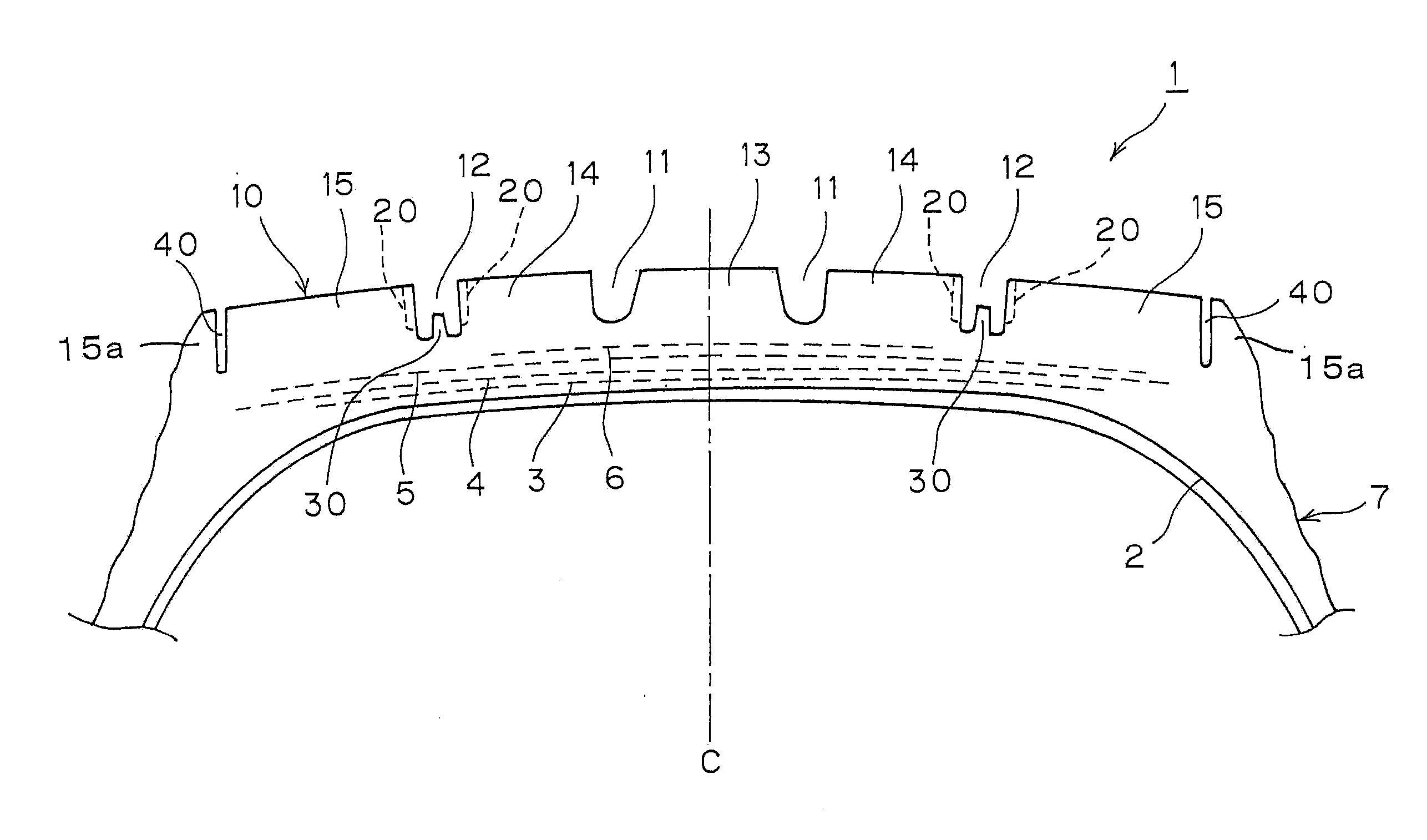
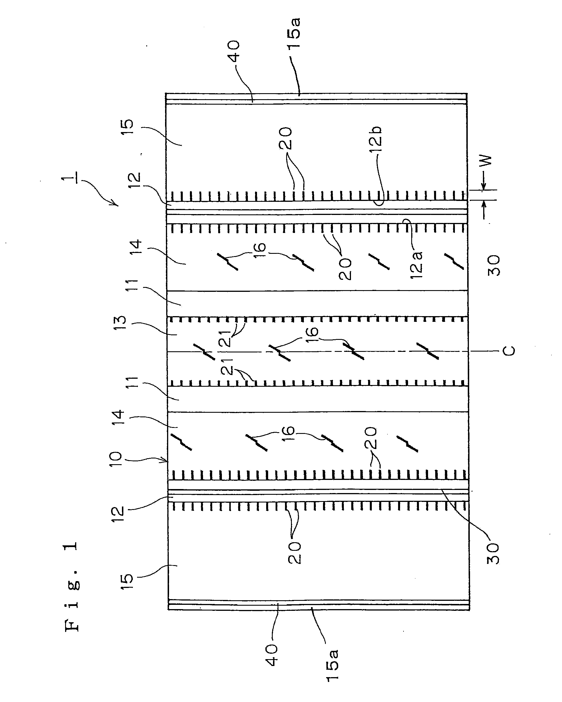
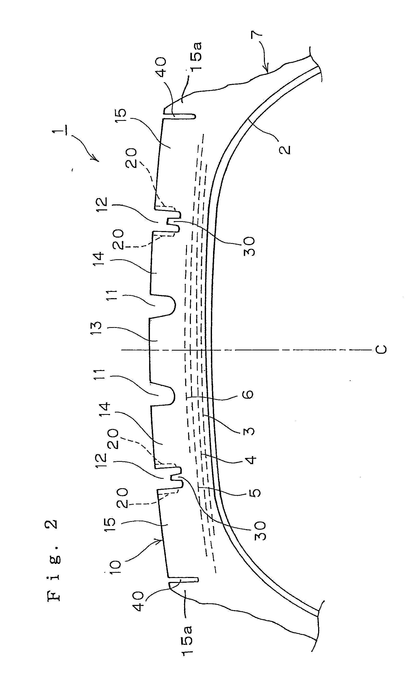
[0051]The following tire performance evaluations were carried out on prototype tires (radial tires of 295 / 75R22.5 which were each made up of a steel carcass of one ply and a steel belt of four plies) which were experimentally produced to each have the tread pattern shown in FIG. 1 and to specifications described in Table 1.

[0052]The following specifications were made common over the prototype tires produced. The width and depth of main grooves 11, 12 were 11 mm and 12 mm, respectively, and the width of any of sipes 20 opened in both groove walls of the main grooves 12 was 0.6 mm, the radius of curvature of a sipe end portion being 0.3 mm. The height of a rising portion 30 was 6.5 mm, and the rising portion 30 was formed into a trapezoidal shape in cross section in which a width at a bottom side was 5 mm and a width at an upper side was 4 mm and was provided in such a manner as to extend continuous...


PUM


Abstract

A pneumatic tire is provided which can realize an increase in stone-catching resistance while suppressing uneven wear such as river wear in a tread portion. In a pneumatic tire in which a center rib and intermediate ribs which are defined by four straight-line main grooves, which extend continuously in a circumferential direction of the tire and shoulder ribs which are defined by the main grooves which are situated closer to shoulders of the tire and straight-line thin grooves which extend continuously in the circumferential direction of the tire in the vicinity of tread ground-contacting edges are formed on the surface of a tread of the tire, inclination angles of a shoulder side groove wall of the main groove which defines the shoulder rib and a tire's equator line side groove wall of the thin groove are both such an angle that the shoulder side groove wall and the tire's equator line side groove wall are inclined at an angle of not more than five degrees in a direction in which the width of a proximal portion of the rib is expanded relative to normal lines to the tread.

Description

BACKGROUND OF THE INVENTION[0001]1. Field of the Invention[0002]The present invention relates to a pneumatic tire of a rib pattern having a plurality of land portions which continue substantially in a circumferential direction of the tire and more particularly to a pneumatic tire which can realize an increase in the stone-catching resistance while suppressing uneven wear, such as river wear, in a tread portion thereof.[0003]2. Description of Related Art[0004]Conventionally, since heavy-load radial tires which are used for trucks and buses are made highly rigid by disposing a belt layer made up of metallic cords in a tread portion and are used with high inflation pressure, with different crown radii R imparted to the tread portion in a tire rotational axis direction, a slipping amount in both shoulder regions to a road surface tends to be increased compared with a central region of the tread portion, and due to this, uneven wear is liable to occur in shoulder-side ribs. As a counterm...

Claims


Application Information

Patent Timeline
Patent Type & Authority Applications(United States)
IPC IPC(8): B60C11/13
CPCB60C11/04B60C2011/1254B60C11/047B60C11/042
Inventor OHARA, MASAAKI
Owner TOYO TIRE & RUBBER CO LTD
Why Eureka
Try Eureka