Organic EL display and manufacturing method thereof

a technology of organic el and manufacturing methods, applied in the direction of discharge tube luminescnet screens, discharge tube/lamp details, coatings, etc., can solve the problems of decreased yield, foreign matter, and inability to easily adhere to the protective layer around foreign matter, so as to improve the sealing properties of organic el elements

Active Publication Date: 2008-06-05
LG DISPLAY CO LTD
View PDF11 Cites 70 Cited by
  • Summary
  • Abstract
  • Description
  • Claims
  • Application Information

AI Technical Summary

Benefits of technology

[0011]According to the invention, since at least a lower part of a foreign matter or a partition wall can be satisfactorily covered with the capping layer, the protective layer can be satisfactorily deposited. Consequently, the sealing properties of the organic EL element can be improved.

Problems solved by technology

However, in the process of manufacturing the organic EL display, foreign matter, such as particles, may be present between the organic EL element and the capping layer.
The protective layer does not easily adhere around such foreign matter, and there may be a case where pinholes are formed in the protective layer.
In such a case, moisture and oxygen in air infiltrate into the organic EL element through the pinholes of the protective layer, thus degrading the organic EL element, resulting in a decrease in the yield.

Method used


Image

  • Organic EL display and manufacturing method thereof
  • Organic EL display and manufacturing method thereof
  • Organic EL display and manufacturing method thereof

Examples


first embodiment

Organic EL Display

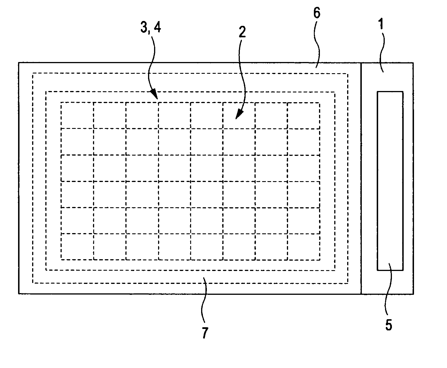
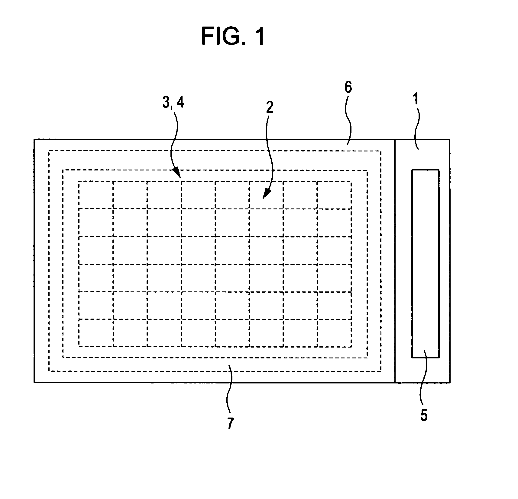
[0023]An organic EL display according to a first embodiment is used in an electric household appliance, such as a television, or an electronic apparatus, such as a mobile phone or a computer device, and includes a planar element substrate 1 and organic EL elements 2 disposed on the element substrate 1, as illustrated in FIG. 1. A capping layer 3 and a protective layer 4 are disposed on the organic EL elements 2.

[0024]The element substrate 1 is composed of glass or plastic. A plurality of organic EL elements 2 are arranged in a matrix on a display region located in the center of the element substrate 1. A driver IC 5 configured to control light emission of the organic EL elements 2 is mounted on a non-display region located at an end of the element substrate 1.

[0025]A cover substrate 6 is disposed on the element substrate 1 so as to be opposed to the element substrate 1. The cover substrate 6 is a transparent substrate and can be composed of, for example, glass or p...

second embodiment

[0058]An organic EL display according to a second embodiment will be described below with reference to FIG. 5. The parts different from the first embodiment will be mainly described.

[0059]In the organic EL display according to the second embodiment, a first protective layer 16, a capping layer 3, and a second protective layer 17 are formed in that order on an upper electrode layer 14. Each of the first protective layer 16 and the second protective layer 17 is composed of, for example, an inorganic material, such as SiNx (04 described above. Each of the first protective layer 16 and the second protective layer 17 is formed by known CVD. The first protective layer 16 and the second protective layer 17 protect the organic EL element 2 from moisture and external air as in the protective layer 4.

[0060]By forming the capping layer 3 on the first protective layer 16, even when the first protective layer 16 has a gap such as a pinhole, the gap can be covered with the capping layer 3. Furthe...

third embodiment

[0062]An organic EL display according to a third embodiment will be described below with reference to FIG. 6. The parts different from the first embodiment will be mainly described.

[0063]In the organic EL display according to the third embodiment, a partition wall 18 having a reversed-tapered shape in which the bottom is narrower than the top is formed on an interlayer insulation film 15, and an organic material layer 3 is formed on the side surface of the partition wall 18.

[0064]When an organic EL element 2 is formed by known vapor deposition, the upper surface of the partition wall 18 functions as an eaves or a mask so that an organic layer 13 and an upper electrode 14 are not continuously formed at the inclined side surface of the partition wall 18. Consequently, the upper electrode layer 14 can be divided into the individual pixels.

[0065]After an organic material layer 3′ is formed on the partition wall 18 and the organic EL element 2 by vapor deposition, a capping layer 3 is fo...


PUM

PropertyMeasurementUnit
refractive indexaaaaaaaaaa
thicknessaaaaaaaaaa

Abstract

An organic EL display comprises an element substrate, an organic EL element formed on the element substrate, comprising an organic layer including a light emitting layer and a pair of electrode layers disposed on both sides of the organic layer. The organic layer comprises a first organic material. The organic EL display further comprises a capping layer comprising a second organic material having a glass transition point lower than one of the first organic material and a protective layer on the capping layer.

Description

CROSS-REFERENCE TO RELATED APPLICATIONS[0001]The present application claims priority of Japanese Patent Application No. 2006-291550, filed on Oct. 26, 2006.” The contents of this application are incorporated herein by reference in their entirety.FIELD OF THE INVENTION[0002]1. Technical Field[0003]The invention relates to an organic EL (electroluminescent) display and a manufacturing method thereof.[0004]2. Description of the Related Art[0005]Generally, an organic EL display has a structure including an organic EL element capable of emitting light disposed on an element substrate, and a protective layer for sealing the organic EL element disposed on the organic EL element. A structure has also been proposed which further includes a capping layer disposed between the organic EL element and the protective layer so that light emitted from the organic EL element is efficiently extracted to the outside (refer to Japanese Unexamined Patent Application Publication No. 2006-173092).[0006]A m...

Claims


Application Information

Patent Timeline
Patent Type & Authority Applications(United States)
IPC IPC(8): H01L51/54C09K11/02
CPCH01L51/5237H10K50/841H10K50/844
Inventor ABE, SHINICHIASANO, MOTOHIKOOGAWA, HIROMITSU
Owner LG DISPLAY CO LTD
Why Eureka
Try Eureka