Multipoint, virtual control, and force based touch screen applications

a touch screen and virtual control technology, applied in the field of multipoint, virtual control, and force based touch screen applications, can solve the problems of limiting the resolution or the size or both of the display to which entry is made, no known commercial device can do, and limited technology set for this purpose, etc., to achieve cost-effective, unique dynamic detection ability, and cost-competitive

Inactive Publication Date: 2008-06-05
TACTILE FEEDBACK TECH
View PDF32 Cites 47 Cited by
  • Summary
  • Abstract
  • Description
  • Claims
  • Application Information

AI Technical Summary

Benefits of technology

[0046]A further advantage of the inventions ability to detect multiple input signatures, etc. at any point on its face, therefore a keyboard, a piano keyboard, a joy stick can be artificially created at any point under computer control or simply by random human command. This is a particular desirability in a car where you cannot necessarily keep your eye on the data entry device or for example for handicapped people who could not be expected to hit the right point on the device every time, but if they just hit the device anywhere, could make a move from that point in a manner that would be intelligible to a computer for example.
[0047]11. Common Systems. In addition to the above advantages over the prior art, the invention also has an advantage that it employs essentially standard hardware for any screen size. The same technology is applicable for a screen or “pad” of say 3″×4″ (8×10 cm) such as might be in a car dashboard all the way to screens or digitizers; the size of a wall. This allows the cost to be reduced as the technology can be shared.
[0048]12. Variable and “Intelligent” orientation. It is also useful therefore to replace in many cases keyboards which have continuous arrays of keys, be they optical, mechanical, contact, electro mechanical or whatever. Unlike most keyboards the disclosed type can “float” (i.e. be at any zone on the surface) which is convenient for people who know how to type but cannot see the keys for example, while driving.
[0049]13. Tactile feedback, including programmable. The unique tactile feedback application aspect of the invention allows one to essentially use a deformable member as a sort of miniature joy stick for each finger or to rock back and forth between one or more fingers to create different signals. In addition, programmable tactile feedback such as air blasts, vibration, etc., can also be added easily to the touch surface.
[0050]14. Another advantage of the invention is that it can detect a force or displacement signature such as of an object that would be picked up by a robot hand. Of interest as well is the ability to sense the signature of someone, even one who would enter a signature of his palm or what have you. This may be of considerable use to the blind and other physically disabled persons, allowing use of non-conventional inputs (e.g. elbows toes, etc) and the tactile feedback afforded is particularly helpful here.
[0051]15. In a gaming and simulation context, the invention has the advantage that it is low in cost, and provides a method by which the game player can participate in a physical way, just as in real sports, and the like.

Problems solved by technology

No known commercial devices can do this, and a limited technology set exists for this purpose—especially over large extensive screen or pad areas.
In addition, conventional technologies typically limit the resolution or the size or both of the display to which entry could be made.
For example, touch screen data entry is commonly available over a standard let us say 12″ to 19″ computer terminal to the level of 1 part in 40 in both X and Y. While this suffices for many computer data entry purposes (e.g. selecting icons), it is certainly not suitable for high resolution drawing on a screen or other such activities.
Prior art is lacking which can accommodate high resolution “touch” or other inputs easily over large surfaces such as for example data displays in military war rooms and the like.
In addition, high resolution seems possible in prior art digitizers only by moving special apparatus or using special writing instruments such as a conductive pen, and high resolution touch screens are difficult with digital technologies such as the discrete grids.
Such grids also run the risk of degrading the light transmission characteristics of the screen.
Another drawback of most conventional data entry systems today is that they can only respond to one point at a time.
Accuracy is also a problem with most digitizers and touch screens, in particular those using analog principles (e.g. the Bowman reference above).
There is virtually no evidence of 3-D capability in the finger touch devices.

Method used


Image

  • Multipoint, virtual control, and force based touch screen applications
  • Multipoint, virtual control, and force based touch screen applications
  • Multipoint, virtual control, and force based touch screen applications

Examples


Embodiment Construction
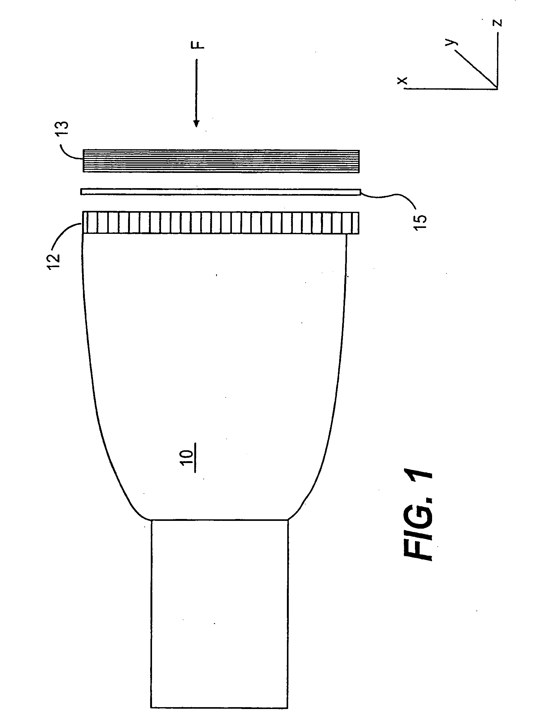
[0082]FIG. 1

[0083]A typical prior art touch screen arrangement which, like the invention, operates in a physical touching mode, is shown in FIG. 1. In this arrangement, a transparent member 12 comprised of a periodic set of conductive bars is placed on the front of CRT tube 10. It is opposed by a second member 13, whose surface includes a set of conducting bars in the orthogonal direction. The two conducting surfaces are separated by a third transparent insulating medium 15, having on array of holes in it which can allow the force of touching to push the front surface through to the rear surface thereby making contact. By scanning the conductors electronically, at the point of contact, a signal is generated which then gives the XY location on the screen of the touch.

[0084]The resolution of the conventional touch screen technology represented by FIG. 1 is limited in that the horizontal / vertical lines must be wide enough spaced so that one can push through without touching adjacent on...


PUM


Abstract

A method and apparatus are provided providing a touch screen having multipoint sensing and / or force based sensing and feedback capability useful in many applications which extend beyond traditional computer applications. The touch screen can be located in many non-traditional locations as well, such as desks, tables, walls, vehicles, and the like. The apparatus may be used by a single user, or multiple users, employing fingers, hands, feet and other body portions, if desired or practical. Related applications for virtual image or physical control applications are also disclosed

Description

CROSS REFERENCE TO RELATED APPLICATIONS[0001]This application is a continuation of application Ser. No. 11 / 495,666 filed Jul. 31, 2006; which is a continuation of application Ser. No. 09 / 435,854 filed Nov. 8, 1999, now U.S. Pat. No. 7,098,891; which is continuation of application Ser. No. 08 / 496,908 filed Jun. 29, 1995, now U.S. Pat. No. 5,982,352. All of these prior applications are hereby incorporated by reference.[0002]The disclosures of the following U.S. patents and patent applications are also incorporated herein by reference:[0003]U.S. Pat. No. 4,629,319 (“D-SIGHT”)[0004]U.S. Pat. No. 4,394,683 (“Circuits”)[0005]U.S. Pat. No. 4,373,804 (“Turbine”)[0006]U.S. Ser. No. 08 / 290,516 filed Aug. 15, 1994 (“Man Machine Interface”)[0007]U.S. Ser. No. 08 / 203,603, filed Feb. 28, 1994 (“Robot Vision Using Target Holes . . . ”)[0008]U.S. Ser. No. 07 / 664,574, filed Mar. 6, 1991 (“Targets II”)[0009]U.S. Ser. No. 07 / 875,282, filed Apr. 29, 1992 (“Vision Target Based Assembly”)[0010]U.S. Ser. ...

Claims


Application Information

Patent Timeline
Patent Type & Authority Applications(United States)
IPC IPC(8): G06F3/041
CPCG06F3/011G06F3/016G06F2203/04109G06F3/0425G06F3/0304
Inventor PRYOR, TIMOTHY R.
Owner TACTILE FEEDBACK TECH
Why Eureka
Try Eureka